Mineral floatation column

A mineral flotation and flotation column technology, applied in flotation, solid separation, etc., can solve the problems of lost recovery rate, lower recovery rate of flotation column, and insufficient mineralization of useful fine-grained materials.

Active Publication Date: 2010-02-10
BGRIMM MACHINERY & AUTOMATION TECH CO LTD
View PDF0 Cites 20 Cited by
  • Summary
  • Abstract
  • Description
  • Claims
  • Application Information

AI Technical Summary

Problems solved by technology

[0003] (1) Insufficient dissociation of minerals can not give full play to its superiority of improving grade; coarse particles have a shorter residence time in the column than pulp, which makes it difficult to suspend coarse particles, the probability of contact between air bubbles and particles is small, and the recovery rate is lost in order to improve the grade ;The use is limited to the selection operation, and the use effect in the roughing operation is not ideal, and the separation size range of the flotation column is relatively narrow;
[0004] (2) The chemical properties of the pulp have a great influence on the flotation effect. The pulp with high viscosity will cause extremely poor tailing foam, which will make the fine-grained gangue stay in it for a long time and deteriorate the flotation process;
[0005] (3) Since the flotation column has no stirring device, the useful fine-grained materials entrained in the slime cannot be fully mineralized, and are taken away by the tailings, reducing the recovery rate of the flotation column

Method used


Image

  • Mineral floatation column
  • Mineral floatation column
  • Mineral floatation column

Examples


Embodiment Construction

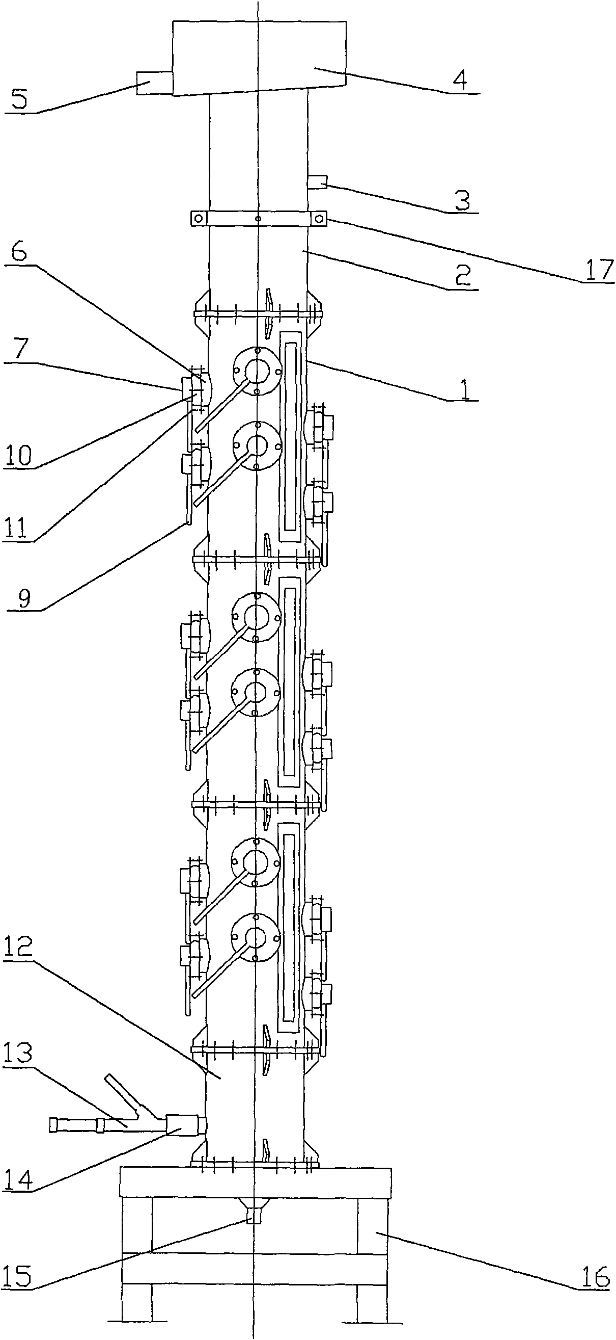
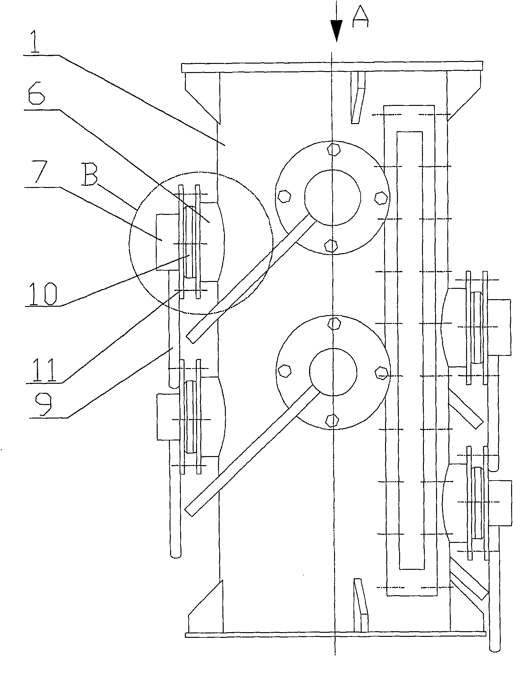
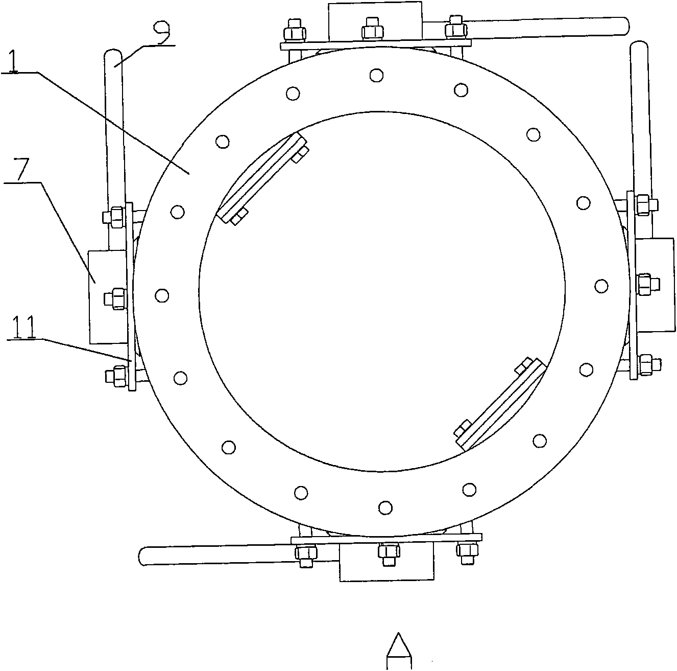
[0031] A kind of mineral flotation column, its structure comprises:

[0032] Flotation column body 1 - the body is a steel tubular body with a circular through-hole and a vertically arranged transparent strip-shaped observation window on the side wall of the body;

[0033] The ore inlet pipe section 2 - the ore inlet pipe section is a joint pipe cylinder with the same diameter as the flotation column body and flanged to the upper end of the flotation column body. A horizontal ore inlet pipe is arranged on the side wall of the ore inlet pipe section 3;

[0034] Foam tank 4 - the foam tank is a hollow tank body with an open upper end, the lower bottom of the tank body has a through hole fixedly connected with the upper end of the ore feeding pipe section, and a foam discharge pipe 5 is opened at the lower part of the side wall of the tank body;

[0035] Ultrasonic generating device mounting seat 6 - the mounting seat is a section tube-shaped seat fixed on the side wall of the f...


PUM


Abstract

The invention relates to a mineral floatation column, in particular to a columnar floatation device for separating minerals in a liquid medium. The columnar floatation device is characterized by structurally comprising a floatation column body, an ultrasonic generating device and a mounting base, wherein the mounting base is fixedly connected to a circular through-hole formed on the lateral wall of the floatation column body; and the ultrasonic generating device is mounted on the mounting base. By taking the unique advantages of the existing floatation column and introducing the ultrasonic technology into the floatation column, materials passing through the floatation column are subject to hydrodynamic force, gravity force, surface chemical force, interaction force among particles, and cavitation and ultrasonic direct-inflow effects generated by ultrasonic waves, so that the invention can strengthen the separation process of materials, extend the size fraction range for the materials of the floatation column to select, stimulate the recycling of coarse-particle materials and improve the separation precision, and meanwhile, the invention can improve the recovery rate of operations and reduce the cost of separation operations. The floatation column is applicable to various separation fields, such as mineral separation, wastewater treatment, petroleum, chemical engineering, environmental protection and the like.

Description

technical field [0001] A mineral flotation column, in particular to a columnar flotation device for mineral separation in a liquid medium. Background technique [0002] The flotation column technology is a high-efficiency flotation separation equipment developed in the 1950s. Its advantages are: one flotation column can replace the multi-stage operations of multiple flotation machines, which simplifies the entire flotation process, and the pulp flow The state is relatively stable, the foam layer is thick, the selectivity is high, there may be no moving parts in the column, the energy consumption is low, the floor space is small, the operation is convenient, and the maintenance cost is low. Flotation columns have many advantages as mentioned above, but also have their own limitations: [0003] (1) Mineral dissociation is insufficient, and its superiority of improving grade cannot be exerted; coarse particles have a shorter residence time in the column than pulp, which makes ...

Claims


Application Information

Patent Timeline
Patent Type & Authority Applications(China)
IPC IPC(8): B03D1/14B03B1/00
Inventor 沈政昌卢世杰史帅星梁殿印陈东杨丽君
Owner BGRIMM MACHINERY & AUTOMATION TECH CO LTD
Why Eureka
Try Eureka