Deformation heat treatment method of petroleum drill pipe friction welding joint

A deformation heat treatment and welded joint technology, applied in welding equipment, non-electric welding equipment, manufacturing tools, etc., can solve the problems of low weld toughness, increase weld brittle failure, reduce weld zone fatigue life, etc. Poor seam toughness, improving production efficiency, and overcoming the effects of low local heat treatment boundary strength

Inactive Publication Date: 2010-02-17
江阴兴鼎石油管具有限公司
View PDF0 Cites 8 Cited by
  • Summary
  • Abstract
  • Description
  • Claims
  • Application Information

AI Technical Summary

Problems solved by technology

[0002] The friction welding process still maintains the fibrous structure of the joint, but changes the streamline direction of the original base metal in the near seam area. This fibrous structure formed by pressure processing is very stable and cannot be eliminated by conventional heat treatment. It exhibits anisotropy It leads to a trough in the toughness of the weld, which reduces the fatigue life of the weld zone and increases the tendency of the brittle failure of the weld during the use of the drill pipe

Method used


Image

  • Deformation heat treatment method of petroleum drill pipe friction welding joint
  • Deformation heat treatment method of petroleum drill pipe friction welding joint
  • Deformation heat treatment method of petroleum drill pipe friction welding joint

Examples


Embodiment Construction

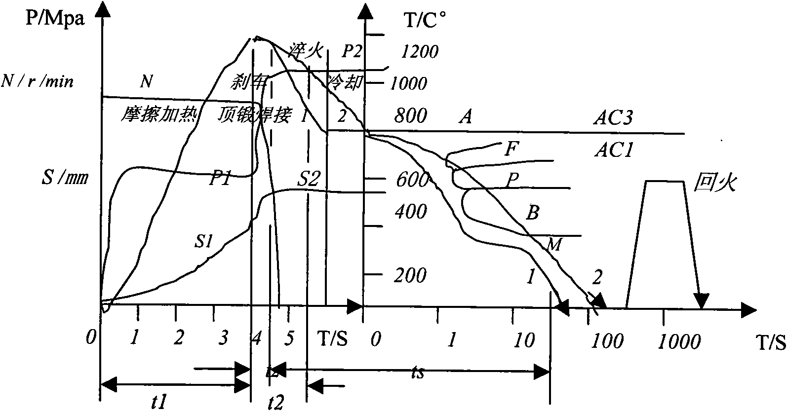
[0009] For the convenience of explanation, the process of direct air cooling after continuous drive friction welding brake upsetting is called ordinary friction welding to show the difference from friction welding deformation heat treatment process. And test the relevant friction welding thermal cycle curve, establish the corresponding continuous cooling structure transition diagram (abbreviated as HCCT diagram, see figure 1 ).

[0010] Depend on figure 1 It can be seen that different thermal cycle curves will correspond to different tissue properties. Curve 1 is the thermodynamic cycle curve of ordinary friction welding. It is not difficult to see that only by adjusting the welding parameters to change its thermal cycle curve is limited. In order to improve the performance of joints, several deformation heat treatment test programs can be designed. Among them, curve 2 is the welding heat quenching test. The welding heat quenching is direct quenching under the local high t...


PUM


Abstract

The invention relates to a deformation heat treatment method of a petroleum drill pipe friction welding joint. The method is characterized in that: a welded friction heating heat source is taken as aheating heat source of welding joint quenching treatment; a joint area is rapidly cooled by using a quenching device arranged on a welder to spray a quenching medium to a welding area in time at a moment after a friction heating stage is finished and before upsetting welding is finished in the process of friction welding; then the welding area is tampered by a tampering device arranged on the welder likewise; and a metal of the welding area is strengthened by both deformation and phase change. Thus, the method can complete friction welding of weldments and hardening and tempering treatment ofthe welding area on the welder and saves three working procedures of annealing, quenching and tempering in the prior welding process. The method improves fatigue life of the welding area and reduces tendency of welding line brittle failure during using the drill pipe.

Description

(1) Technical field [0001] The invention relates to a hydraulic metal baler. It is mainly used to pack cold-state bundles of various light and thin ferrous and non-ferrous metal scraps to form compact and uniform cylindrical bales. It belongs to the technical field of metal balers. (2) Background technology [0002] The friction welding process still maintains the fibrous structure of the joint, but changes the streamline direction of the original base metal in the near seam area. This fibrous structure formed by pressure processing is very stable and cannot be eliminated by conventional heat treatment. It exhibits anisotropy This leads to a trough in the toughness of the weld, which reduces the fatigue life of the weld zone and increases the tendency of the brittle failure of the weld during the use of the drill pipe. (3) Contents of the invention [0003] The object of the present invention is to overcome the above-mentioned disadvantages, and provide a method for the ...

Claims


Application Information

Patent Timeline
Patent Type & Authority Applications(China)
IPC IPC(8): C21D1/18B23K20/26
Inventor 朱庆华郭磊
Owner 江阴兴鼎石油管具有限公司
Why Eureka
Try Eureka