Core rod of insulator and manufacturing method thereof

A manufacturing method and technology of insulators, applied in the direction of insulators, supporting insulators, electrical components, etc., can solve the problems of increasing the man-hours of operators, complex spacer structures, and complicated processes

Inactive Publication Date: 2010-02-17
浙江科成电气有限公司
View PDF1 Cites 4 Cited by
  • Summary
  • Abstract
  • Description
  • Claims
  • Application Information

AI Technical Summary

Problems solved by technology

The first is to use epoxy resin glass fiber solid lead rod. Due to the limitation of the existing epoxy resin glass fiber technology, it is difficult for the pillar composite insulator produced with solid mandrel to meet the requirements of the isolation switch pillar with a voltage level above 220kV. Requirements for bending and torsion resistance, and the production cost, transportation and installation costs of the pillar composite insulator produced by the solid mandrel are relatively high
The other is a hollow mandrel, and the mandrel is filled with sulfur hexafluoride gas. The main problem of the post composite insulator produced by this mandrel is that it is often necessary to detect the content of sulfur hexafluoride gas in the mandrel, resulting in Inconvenience in use, and sulfur hexafluoride gas also has a certain impact on the environment
[0005] Although the above-mentioned mandrels ov

Method used


Image

  • Core rod of insulator and manufacturing method thereof
  • Core rod of insulator and manufacturing method thereof
  • Core rod of insulator and manufacturing method thereof

Examples


Embodiment 1

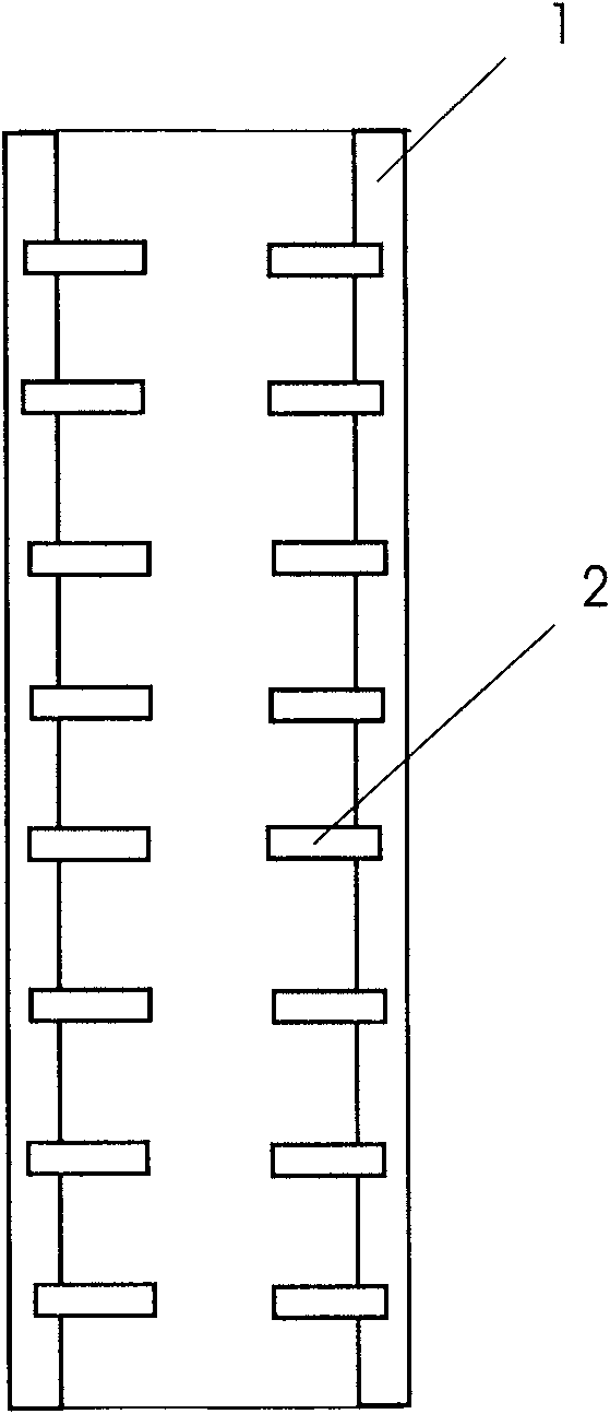
[0024] Embodiment one: see figure 1 , all the spacers 2 embedded in the hollow rod 1 are disc-shaped.

Embodiment 2

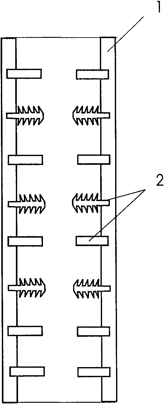
[0025] Embodiment two: see figure 2 , among the spacers 2 embedded in the hollow rod 1, the spacers 2 near the two ends of the hollow rod 1 are disc-shaped, and the rest of the spacers 2 are disc-shaped, or the two end surfaces of the discs have a bevel shape.

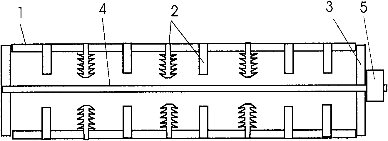
[0026] The manufacturing method of above-mentioned insulator mandrel, it comprises the following steps:

[0027] a) Production of the spacer: according to the requirements of the mandrel to be made, the spacer is made. The spacer 2 can be disc-shaped, or the spacer 2 near the two ends of the hollow rod 1 is disc-shaped, and the remaining spacers 2 are disc-shaped. The shape of a disc, or the two ends of the disc have a bevel shape, and the material of the spacer 2 is EPBS to enhance the hardness of the spacer. The spacer 2 can be made by pressing a corresponding mold on a flat vulcanizing machine.

[0028] b) Production of the base pipe: the epoxy resin and glass fiber composite base pipe are made by pultrusion, the...


PUM


Abstract

The invention discloses a core rod of an insulator, comprising a hollow rod body and a plurality of partition blocks, wherein the hollow rod body is compounded by ethoxyline resins and glass fibres; the partition blocks are vertically embedded into the hollow rod body in the hollow rod body and can be all in a light disk shape, or the partition blocks close to both ends of the hollow rod body arein a light disk shape, and other partition blocks are in a light disk shape or a shape that both end surfaces of the light disk are provided with bevel teeth. A manufacturing method of the core rod comprises the following steps: (a) manufacturing the partition blocks, i.e. manufacturing the partition blocks according to the requirement of the core rod which needs to be manufactured; (b) manufacturing a base pipe, i.e. manufacturing the base pipe in a squeezing and pulling way; (c) cutting, i.e. cutting the base pipe on a position needing to install the partition blocks; (d) fixing, i.e. placing the partition blocks on the cutting position of the base pipe; (e) thickening, i.e. squeezing and pulling the core rod till the outer diameter of the core rod is equal to that of the code rod whichneeds to be manufactured. Because the plurality of partition blocks are embedded into the hollow rod body, the core rod of the insulator has the simple structures of the partition blocks and also saves materials consumed by a connection structure; and in addition, the technology is simple in a manufacturing method aspect.

Description

technical field [0001] The invention relates to an insulator used in high-voltage electric transmission equipment, more specifically an insulator mandrel and a manufacturing method thereof, belonging to the technical field of electric equipment. Background technique [0002] Insulators are necessary for high-voltage and ultra-high-voltage power transmission lines. At the earliest, there were only porcelain and glass insulators. By the 1970s, high-temperature vulcanized silicone rubber composite insulators were first introduced in Germany. Compared with traditional insulators such as porcelain and glass, It has the advantages of light weight, high strength, strong pollution flashover resistance, convenient maintenance and transportation. In recent years, composite line post insulators have also developed rapidly in our country. [0003] Existing pillar composite insulators are composed of upper and lower metal accessories, core rods and umbrella skirts outside the core rods....

Claims


Application Information

Patent Timeline
IPC IPC(8): H01B17/38H01B17/14H01B19/00
Inventor 章银龙马银海丁调娟严峰
Owner 浙江科成电气有限公司
Why Eureka
Try Eureka