Process flow for removing CO2 and H2S in gas mixture

A technology of process flow and mixed gas, which is applied in the comprehensive purification treatment of shift gas in methanol production and in the field of comprehensive purification treatment of shift gas in the production of synthetic ammonia and co-production of urea, which can solve the problem of high device operating costs, large equipment investment, and inability to apply sulfur Recycling and other issues to achieve the effect of recycling and improving economic and social benefits

Active Publication Date: 2010-02-24
成都华西工业气体有限公司
View PDF8 Cites 10 Cited by
  • Summary
  • Abstract
  • Description
  • Claims
  • Application Information

AI Technical Summary

Problems solved by technology

Although this method is effective for shifting CO in the gas 2 The impurities were removed and recovered, but the H in the shift gas was not 2 S proposes a recycling plan, while H 2 S mixed with CO 2 Product gas also affects CO 2 Product gas purity and potential adverse effects on subsequent processes
Invention patent ZL200310104007.X and invention patent ZL01108694.7 also respectively provide a pressure swing adsorption decarburization method for synthetic ammonia shift gas in the production of synthetic ammonia and co-production of urea. 2 Purification and separation of effective components of hydrogen and nitrogen in the shift gas, but the two also have no effect on the H in the shift gas 2 S proposes a separate separation and recovery plan
First of all, the equipment investment is large. Due to the long process flow of the low-temperature methanol washing process and the derivative Claus process, a larg...

Method used


Image

  • Process flow for removing CO2 and H2S in gas mixture

Examples


Embodiment 1

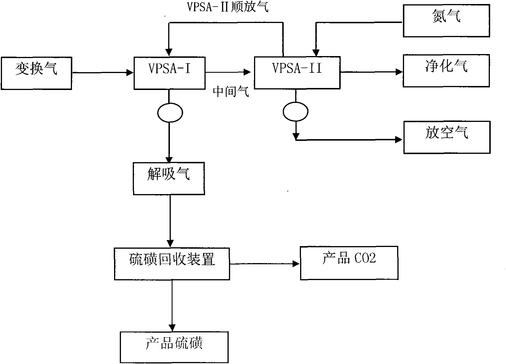
[0015] Taking the shift gas in the process of coal gasification to synthesize ammonia and co-produce urea as the mixed gas to be purified, and its purification process as an example, combined with figure 1 The present invention will be described.

[0016] A synthetic ammonia co-production urea unit using coal as raw material, the composition (v / v) of the shift gas is: CO 2 27.5%, CO 1.5%, H 2 54%, CH 4 0.8%, N 2 16%; H 2 S content: ≤240mg / Nm 3 . The shifted gas is purified by the first stage of vacuum pressure swing adsorption VPSA-I, and the formed intermediate gas enters the second stage of vacuum pressure swing adsorption VPSA-II. CO in intermediate gas 2 The concentration is about 4.6-7.4%, and the removed CO 2 and H 2 S forms desorbed gas by reverse discharge and vacuuming, and in the desorbed gas, CO2 The concentration is about 98.0%. Use H 2 S selective oxidation catalyst for desorbing H in gas 2 S is subjected to selective catalytic oxidation treatment,...

Embodiment 2

[0019] Taking the mixed gas composed of shifted gas and unshifted water gas in the coal gasification to methanol process as the mixed gas to be purified, and the process of purifying it as an example, combined with figure 1 The present invention will be described.

[0020] A coal-to-methanol plant uses Texaco coal-water slurry gasification to produce water gas, and then undergoes partial conversion and gas purification to synthesize methanol. The mixed gas (mixed with converted gas and unconverted crude gas) entering the purification section is as follows (v / v): H 2 43.8%, CO 19.1%, CO 2 34.4%, H 2 S 1.3%, other 1.4%. The purification section adopts the mixed gas provided by the present invention to remove CO 2 、H 2 S craft. First, the shifted gas is purified by the first stage of vacuum pressure swing adsorption VPSA-I, and the formed intermediate gas enters the second stage of vacuum pressure swing adsorption VPSA-II to control the CO in the intermediate gas. 2 Conce...


PUM


Abstract

The present invention provides a process flow for removing CO2 and H2S in gas mixture. The invention is characterized in that the process flow satisfies the high recovery rate requirement to the effective component in the purifying process of the gas mixture which contains the impurities of CO2 and H2S, satisfies the high recovery rate requirement to the effective component in the purifying process of the gas mixture which comprises CO2 and H2S, and realizes the recovery of sulfur product and high-concentration CO2 thereby effectively increasing the economic and social benefit of the gas mixture purifier.

Description

technical field [0001] The invention relates to a method for removing CO from mixed gas 2 、H 2 The technological process of S is mainly used for the treatment of CO 2 、H 2 The comprehensive purification treatment of the mixed gas of S impurities is especially suitable for the comprehensive purification treatment of the shift gas in the production of synthetic ammonia and co-production of urea and the comprehensive purification treatment of the shift gas in the production of methanol. Background technique [0002] Contains CO 2 、H 2 The mixed gas of S, especially the shift gas in the production of synthetic ammonia and methanol, needs to remove the CO in order to meet the needs of subsequent processes 2 、H 2 S and other impurities. Due to the advantages of simple process, low investment, simple operation, low operating cost, and simultaneous removal of CO, pressure swing adsorption technology 2 、H 2 The characteristics of impurities such as S have been widely used, e...

Claims


Application Information

Patent Timeline
IPC IPC(8): B01D53/047
CPCY02C10/08Y02C20/40
Inventor 李东林王俊昌郎治
Owner 成都华西工业气体有限公司
Why Eureka
Try Eureka