Multiparameter automatic control method of industrial furnace burner

A technology for industrial furnaces and burners, applied in the control of combustion, lighting and heating equipment, etc., can solve the problems of difficult to achieve the requirements of straight pipe sections, requirements of compact structure, large opening of the air door, etc., to achieve the best combustion effect, avoid Structured effects

Active Publication Date: 2010-02-24
江苏焱鑫科技股份有限公司
View PDF0 Cites 35 Cited by
  • Summary
  • Abstract
  • Description
  • Claims
  • Application Information

AI Technical Summary

Problems solved by technology

This kind of control cannot realize the precise control of the fuel to the amount of combustion-supporting air during the combustion process.
In order to ensure full combustion, the combustion-supporting air volume control damper is manually controlled. In industrial applications, the burner damper opening is often large. Regardless of the change in fuel volume, the damper opening can always meet the requirements of the combustion process for combustion-supporting air or oxygen. In this way, it is difficult to ach

Method used


Image

  • Multiparameter automatic control method of industrial furnace burner
  • Multiparameter automatic control method of industrial furnace burner
  • Multiparameter automatic control method of industrial furnace burner

Examples


Embodiment 1

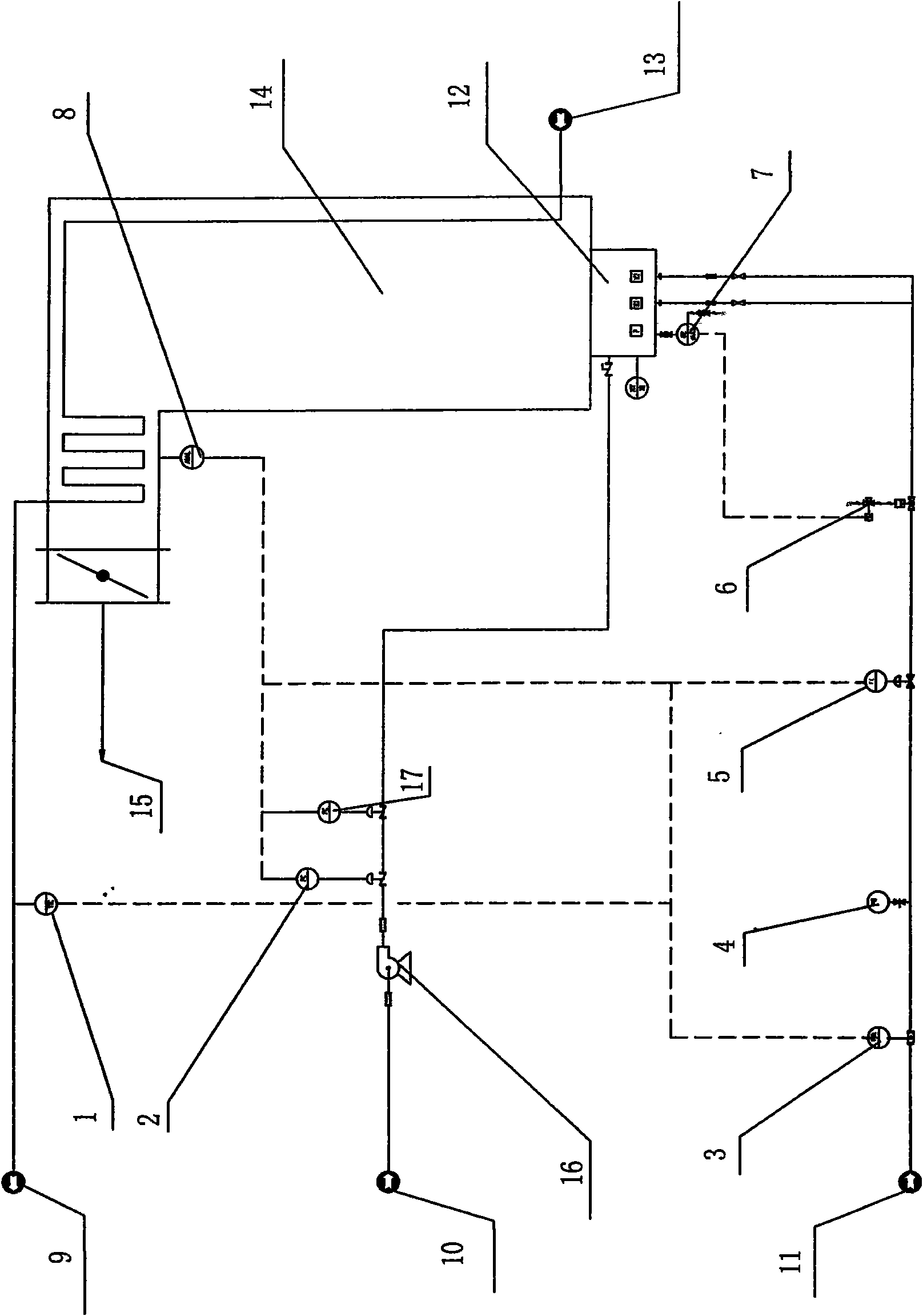
[0017] see figure 1 , figure 1 It is a schematic diagram of the multi-parameter automatic control method of the industrial furnace burner of the present invention. Depend on figure 1 It can be seen that the multi-parameter automatic control method of the industrial furnace burner of the present invention is that the fuel flow display control instrument 3, the fuel pressure control instrument 3, and the fuel pressure are sequentially installed on the fuel feed line 11 of the industrial furnace burner along the fuel feed direction. Table 4, fuel flow regulating valve 5 and flameout protection solenoid valve 6; a flame detector 7 is installed on the industrial furnace burner 12, and the flame detector 7 is connected with the control signal of the flameout protection solenoid valve 6; A furnace tube or furnace outlet temperature display control instrument 1 is installed on the outlet pipeline 9, and the furnace tube or furnace outlet temperature display control instrument 1 is r...

Embodiment 2

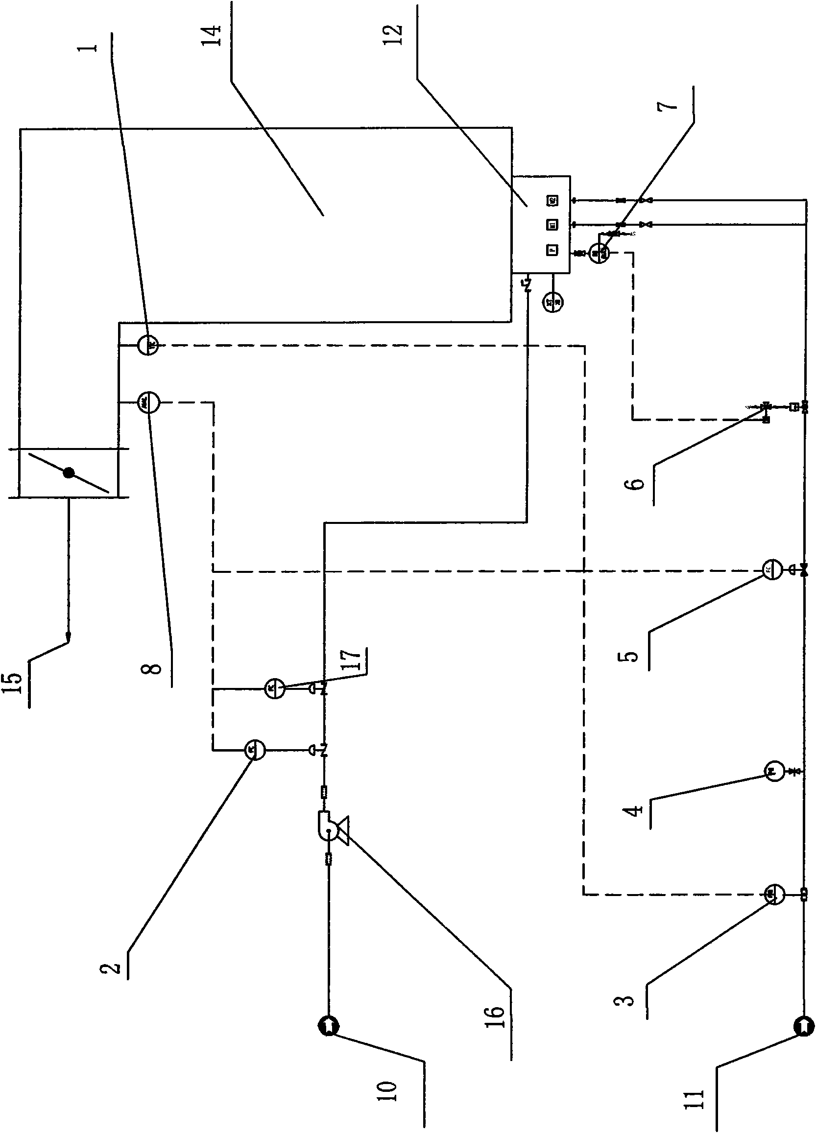
[0020] Example 2 as figure 2 As shown, it differs from Embodiment 1 only in that: the furnace tube or furnace outlet temperature display control instrument 1 is installed on the flue gas of the industrial furnace 14 from the furnace or its outlet.

Embodiment 3

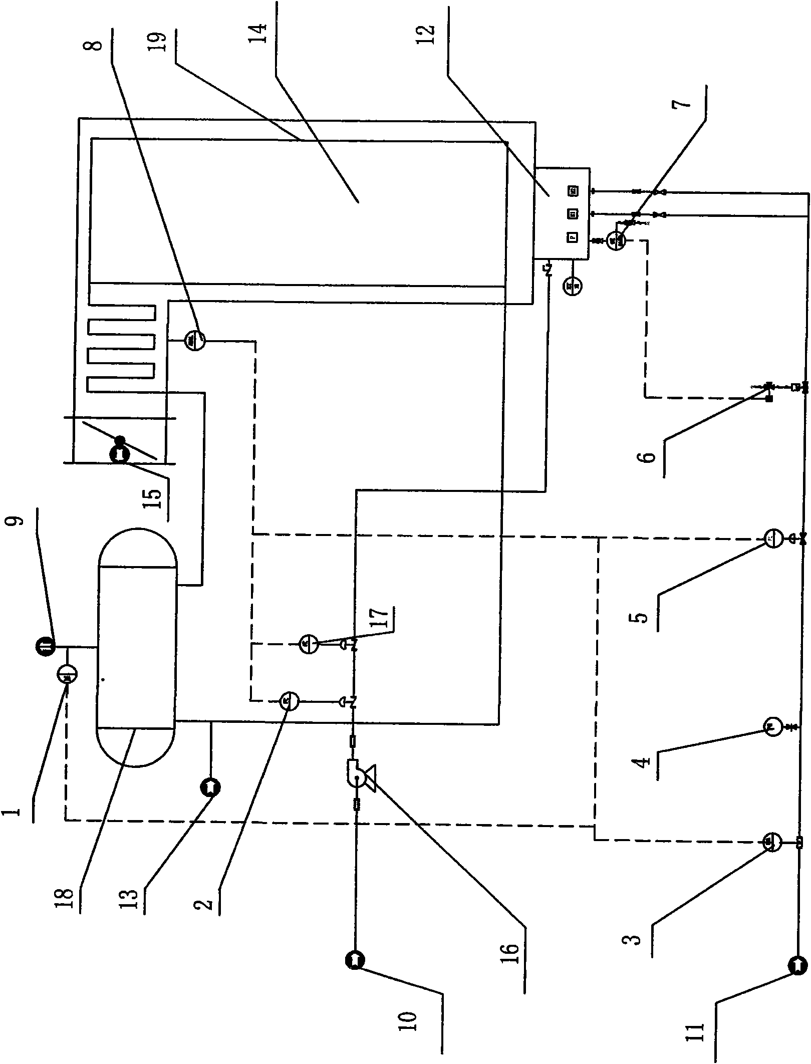
[0022] Example 3 as image 3 As shown, it differs from Embodiment 1 only in that: the furnace tube or furnace outlet temperature display control instrument 1 is installed on the steam or hot water outlet pipeline where the boiler tube of the industrial furnace 14 communicates with the steam drum 18 .


PUM


Abstract

The invention relates to a multiparameter automatic control method of an industrial furnace burner. A temperature parameter measured by a furnace tube or a hearth outlet temperature display control meter is utilized to control a fuel flow control valve of fuel supply volume; a fuel pressure gauge of the fuel supply volume judges whether the fuel pressure satisfies the combustion demand or not; a parameter of a fuel flow display control meter on a supplied fuel feed pipeline provides a control parameter for a combustion-supporting gas flow control regulator valve; combustion-supporting air amount is regulated proportionally; then an oxygen content parameter measured by an on-line analysis sensor of a fume detector of a furnace fume outlet serves as the control parameter of the combustion-supporting gas flow control regulator valve so as to regulate an upper limit value control parameter of the combustion-supporting air amount or the oxygen content; and a carbon monoxide or fuel composition content parameter measured by the on-line analysis sensor of the furnace outlet fume detector serves as the control parameter of the combustion-supporting gas flow control regulator valve so as toregulate a lower limit value control parameter of the combustion-supporting air amount or the oxygen content. The method can meet the accurate control demand of the fuel on the combustion-supportingair amount in the combustion process.

Description

(1) Technical field [0001] The invention relates to a method for controlling an industrial furnace burner. It is mainly used for the control of automatic burners in industrial heating furnaces. It can be used in industrial furnaces in petroleum, petrochemical, coal chemical, metallurgy, ceramics, building materials and other fields. It belongs to the technical field of automatic control of industrial furnace burners. (2) Background technology [0002] The industrial furnace burner is a key component to realize the combustion of fuel in the industrial furnace. The control that can be realized is to use the material outlet temperature parameter to control the fuel quantity parameter, plus flameout protection, to form a control scheme for automatically controlling the burner. Such control cannot realize the precise control requirement of the fuel for the amount of combustion-supporting air in the combustion process. In order to ensure full combustion, the combustion-supporti...

Claims


Application Information

Patent Timeline
IPC IPC(8): F23N5/00
Inventor 葛京鹏卢康黄凯华贡程红李华陈亿贡海荣李艳军赵德平龚秋平陶科生周剑刘青贡菁菁季科敏
Owner 江苏焱鑫科技股份有限公司
Why Eureka
Try Eureka