An integrated marine energy development system

A technology for developing systems and oceans, which is applied in the fields of ocean energy power generation, fluid extraction, and mineral extraction. Development areas and realizing the effect of deep sea storage

Active Publication Date: 2011-12-07
CHINA NAT OFFSHORE OIL CORP +1
View PDF0 Cites 0 Cited by
  • Summary
  • Abstract
  • Description
  • Claims
  • Application Information

AI Technical Summary

Problems solved by technology

However, after a period of time, due to the heat absorption of natural gas hydrate decomposition, the energy of the formation is reduced, the decomposition rate of natural gas hydrate slows down, and even the formation water freezes and the secondary generation of natural gas hydrate forces the production to be interrupted; in addition, the natural gas hydrate decomposition also It will make the natural gas hydrate formation deficient, the formation will subside, and threaten the offshore engineering facilities, so there will be a big safety hazard
The chemical agent injection method is to inject some chemical solutions into the gas hydrate layer, and these chemical substances can make the gas hydrate unstable and decompose. The cost of injecting chemical agents is too high, and it will cause a certain degree of pollution to the marine environment
The current heat injection method is mainly to inject high-temperature hot water and high-temperature steam heated on the production platform or on the ground into the natural gas hydrate layer; however, heating hot water and steam on the production platform or on the ground requires a lot of energy, which leads to The heat injection method has high cost and complex equipment, which makes the economics of natural gas hydrate production unfavorable

Method used


Image

  • An integrated marine energy development system
  • An integrated marine energy development system
  • An integrated marine energy development system

Examples


Embodiment Construction

[0017] The present invention will be described in detail below in conjunction with the accompanying drawings and embodiments.

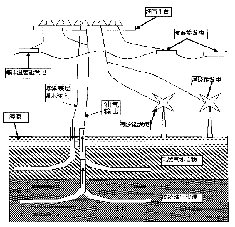
[0018] The marine energy integrated development system of the present invention relies on marine oil and gas production facilities as the main platform, utilizes wave energy, wind energy and ocean temperature difference energy to generate electricity within the scope of the control of marine production facilities, installs power generation facilities on the seabed, and makes full use of seabed tides and oceans. Ocean currents generate electricity. Such as figure 1 As shown, the marine energy integrated development system of the present invention includes a wave energy power generation module 1, a traditional oil and gas production module 2, an ocean temperature difference energy power generation module 3, a tidal and ocean current underwater power generation module 4 and a seabed natural gas hydrate exploitation module 5. Wave energy power generation...


PUM


Abstract

The invention relates to an integrated marine energy development system, which is characterized in that it includes a wave energy power generation module, a traditional oil and gas production module, an ocean temperature difference energy power generation module, a tidal and ocean current underwater power generation module, and a seabed natural gas hydrate exploitation module; The power generation module uses ocean waves to generate electricity, the ocean temperature difference power generation module uses ocean temperature differences to generate electricity, and the tide and ocean current underwater power generation module uses tides and ocean currents to generate electricity; traditional oil and gas production modules and wave energy power generation modules, ocean temperature difference power generation modules, tides and ocean current water The lower power generation module shares living infrastructure and power infrastructure, and shares drilling rig equipment and submarine oil and gas pipelines with the subsea natural gas hydrate exploitation module; the electric energy output by the wave energy power generation module, ocean temperature difference energy The cables of the submarine oil and gas pipeline are exported; the natural gas hydrate exploitation module exploits natural gas hydrate through the ocean surface warm water injection method and carbon dioxide replacement method.

Description

technical field [0001] The invention relates to a marine energy exploitation device, in particular to an integrated marine energy development system. Background technique [0002] At present, the global offshore oil and gas resources account for 34% of the total global oil resources. The accumulated proven reserves are about 40 billion tons, and the proven rate is about 30%. It is still in the early stage of exploration. Therefore, in the foreseeable future, the traditional petroleum industry The growth point of oil and gas will be in the marine field. At the same time, the ocean also contains abundant new energy sources, such as natural gas hydrate, tidal energy, surging ocean currents, wind energy, and ocean temperature difference energy. Due to the depletion of traditional oil and gas energy sources, the slowdown in the growth rate of newly discovered reserves of oil and gas resources, the surge in energy demand for rapid economic development, and the increasing emphasis...

Claims


Application Information

Patent Timeline
Patent Type & Authority Patents(China)
IPC IPC(8): F03G7/05F03B13/14F03B13/26E21C50/00
CPCY02E10/38Y02E10/34E21B41/0099Y02E10/30
Inventor 白玉湖李清平
Owner CHINA NAT OFFSHORE OIL CORP
Why Eureka
Try Eureka