System and method for delivering cryogenic fluid

A low-temperature fluid and delivery system technology, applied in container discharge methods, fluid transfer, fluid treatment, etc., can solve problems such as pollution, water accumulation, etc.

Inactive Publication Date: 2010-03-17
NITROCISION
View PDF0 Cites 8 Cited by
  • Summary
  • Abstract
  • Description
  • Claims
  • Application Information

AI Technical Summary

Problems solved by technology

However, water jet machining may suffer from problems related to the accumulation of water during the machining operation or to the potential contamination of the surrounding environment or water by the material removed from the workpiece

Method used


Image

  • System and method for delivering cryogenic fluid
  • System and method for delivering cryogenic fluid
  • System and method for delivering cryogenic fluid

Examples


Embodiment Construction

[0019] by referring to the attached Figures 1 to 9B , embodiments of the invention and some of their advantages will be best understood, wherein like numerals are used for like and corresponding parts of the various drawings.

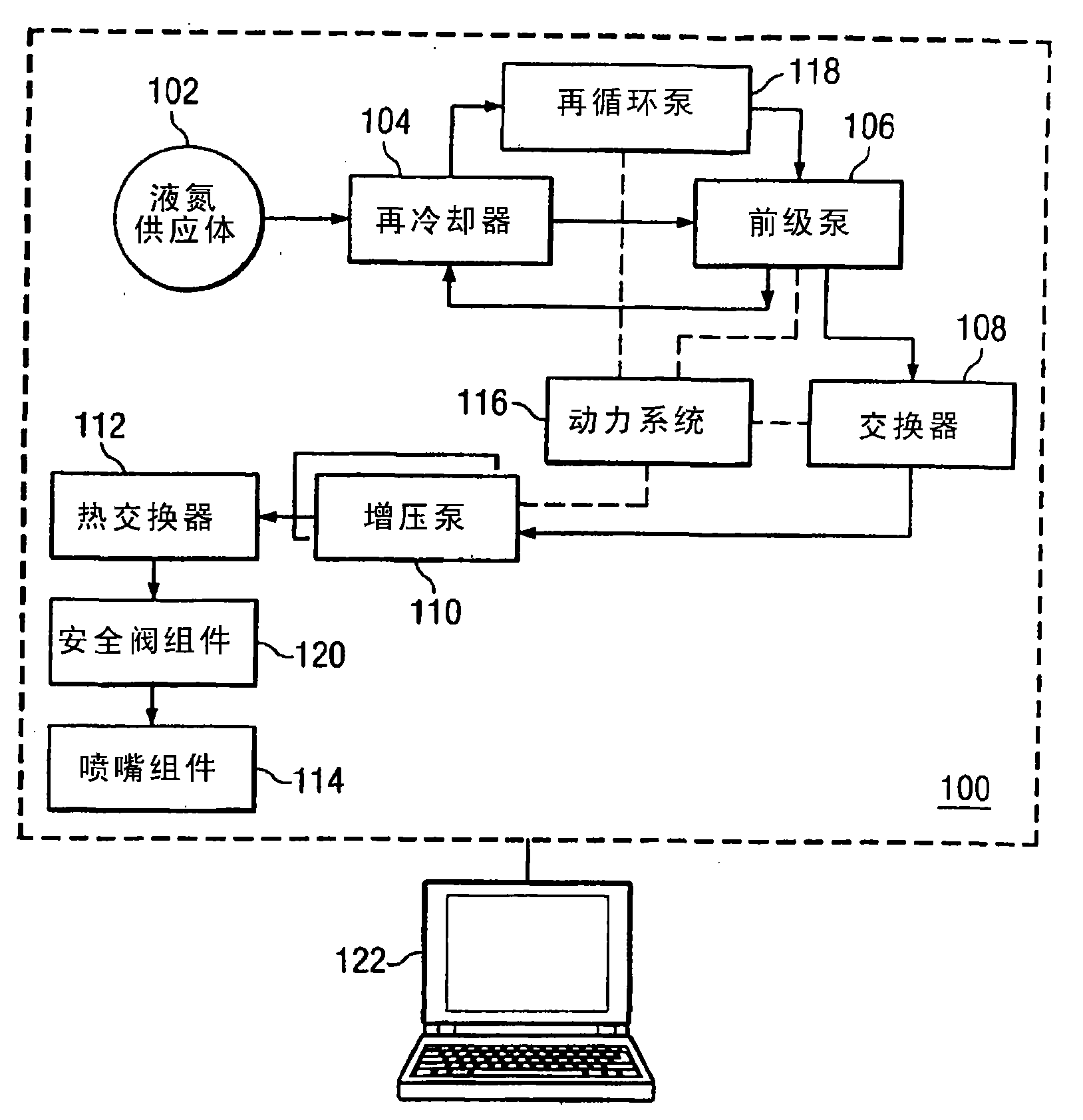
[0020] figure 1 is a functional block diagram of a cryogenic fluid delivery system 100 according to one embodiment of the present invention. In the illustrated embodiment, the delivery system 100 includes a liquid nitrogen supply 102, a subcooler 104, a backing pump 106, an exchanger 108, a pair of booster pumps 110, a heat exchanger 112, a nozzle assembly 114, a power system 116 , recirculation pump 118 , safety valve assembly 120 and controller 122 . However, the present invention also contemplates having more than, less than or different figure 1 The delivery system 100 of those components is shown. In general, the cryogenic fluid delivery system 100 is capable of providing high pressure, high velocity flow of cryogenic fluid to cut, grind, or o...


PUM

PropertyMeasurementUnit
temperatureaaaaaaaaaa
diameteraaaaaaaaaa

Abstract

The invention discloses a system and a method for delivering cryogenic fluid. The cryogenic fluid delivery system includes a vessel containing a cryogenic fluid at a first pressure and a first temperature, a first heat exchanger coupled to the vessel for receiving the cryogenic fluid and cooling the cryogenic fluid to a second temperature, a first pump coupled to the first heat exchanger for pressurizing the cryogenic fluid to a second pressure, a second pump for pressurizing the cryogenic fluid to a third pressure, a second heat exchanger coupled to the second pump for cooling the cryogenic fluid to a third temperature, and a nozzle coupled to the second heat exchanger for delivering a jet of the cryogenic fluid toward a target.

Description

[0001] This application is a divisional application of a patent application with an application date of July 8, 2005, an application number of 200580029752.X, and an invention title of "System and Method for Transporting Cryogenic Fluid". technical field [0002] The present invention relates generally to fluid power machining and, more particularly, to systems and methods for conveying cryogenic fluids. Background technique [0003] In hydrodynamic machining, forces due to changes in momentum of a fluid stream are used to cut, grind or otherwise process material. For example, water is often used as a fluid to cut or grind certain materials, and various abrasive materials can be used to enhance material removal. However, water jet machining may suffer from problems related to the accumulation of water during the machining operation or to potential contamination of the surrounding environment or water by material removed from the workpiece. [0004] In order to solve the afo...

Claims


Application Information

Patent Timeline
Patent Type & Authority Applications(China)
IPC IPC(8): F17C7/04F04B15/08
CPCF17C2205/0332F17C2221/03F17C2225/0169F04B41/02F04B2015/0818F17C2227/0185F17C2250/0439F16L27/0828F16L27/08F17C2221/013F17C2225/036F17C9/02F17C2227/0339F17C2250/0417F17C2225/0115F17C2203/0629F17C2205/0323F17C2223/0161B24C1/003F17C2250/0434F17C2223/033F17C2265/04F17C2227/0388F17C2227/0135F17C2270/05F17C2221/014B05B15/10F04B15/08F17C2250/0413F17C2223/0123F17C2223/0115F17C2265/017F04B2015/0824F17C7/04F17C2250/032
Inventor 霍华德·R·休姆罗纳德·R·沃耐克加里·L·帕默莱斯利·J·费克特
Owner NITROCISION
Why Eureka
Try Eureka