
Fabricating method of shallow trench isolation structure

A shallow trench isolation and manufacturing method technology, applied in the field of shallow trench isolation structure, can solve problems such as easy leakage current, lower device reliability, and increase active area leakage, so as to meet technical requirements, reduce leakage opportunities, The effect of improving electrical performance

Inactive Publication Date: 2010-03-17
GRACE SEMICON MFG CORP
View PDF4 Cites 9 Cited by
  • Summary
  • Abstract
  • Description
  • Claims
  • Application Information

AI Technical Summary

Problems solved by technology

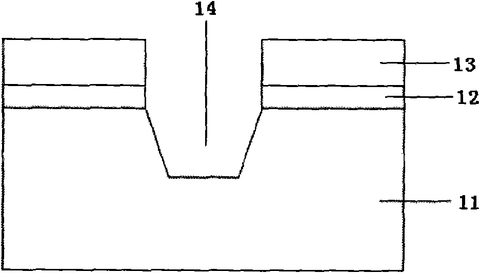
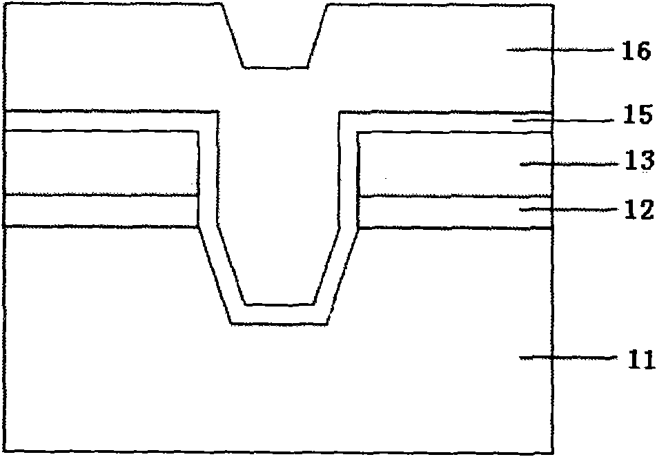
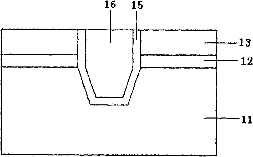
[0008] from Figure 1E It can be seen that the top corner (top corner) 18 of the shallow trench is sharp, and leakage current is easily generated at the sharp corner 18, thereby increasing the chance of leakage between active regions and seriously affecting the electrical performance of the semiconductor device. reduces the reliability of the device

Method used


Image

  • Fabricating method of shallow trench isolation structure
  • Fabricating method of shallow trench isolation structure
  • Fabricating method of shallow trench isolation structure

Examples


Embodiment Construction

[0020] The following will combine Figure 2A ~ Figure 2K The manufacturing method of the shallow trench isolation structure of the present invention is further described in detail.

[0021] A specific embodiment will now be used to describe the manufacturing method of the shallow trench isolation structure of the present invention in detail.

[0022] The manufacturing method of the shallow groove isolation structure of the present invention comprises the following steps:

[0023] Step 1, a pad oxide layer 41 and a hard mask layer (hard mask) 42 are sequentially formed on the surface of the substrate 2, such as Figure 2A shown;

[0024] The pad oxide layer 41 is usually a silicon oxide layer formed by a thermal oxidation process or a silicon oxide layer formed by a high density plasma chemical vapor deposition (High Density Plasma Chemical Vapor Deposition, HDPCVD) process, and the hard mask layer For example, a silicon nitride layer formed by a chemical vapor deposition pr...


PUM

PropertyMeasurementUnit
Thicknessaaaaaaaaaa

Abstract

A fabricating method of a shallow trench isolation structure of the invention comprises the following steps: forming a pad oxide layer and a hard mask layer in sequence on the surface of a substrate;etching the pad oxide layer and the hard mask layer in sequence to form an opening; depositing oxide layers on the surface of the hard mask layer and in the opening; removing the oxide layer on the surface of the hard mask layer and part of the oxide layer on the surface of the substrate by etching and forming self-aligned spacers at two sides of the opening; taking the self-aligned spacers as masks and etching a shallow trench in the substrate; removing the self-aligned spacers to fully expose the sharp top corner of the shallow trench; generating linear oxides in the shallow trench to fullyround the sharp top corner of the shallow trench in the process; filling insulating media in the shallow trench; and removing the hard mask layer and the pad oxide layer to form the shallow trench isolation structure. By adopting the method of the invention, the rounding top corner can be formed at the top of the shallow trench isolation structure to avoid leakage current from occurring.

Description

technical field [0001] The invention relates to semiconductor manufacturing technology, in particular to a method for manufacturing a shallow trench isolation structure. Background technique [0002] Shallow trench isolation (STI) is a process for forming isolation regions between active regions of transistors on a substrate. [0003] The manufacturing method of the shallow trench isolation structure in the prior art is: see Figure 1A , grow a pad oxide layer 12 (pad oxide) on the substrate 11, deposit a hard mask layer (hard mask) 13 on the pad oxide layer 12, make a pattern by photolithography, and then dry etch (dry etch) sequentially etch the hard mask layer 13 , the pad oxide layer 12 and the substrate 11 until a shallow trench 14 is etched in the substrate 11 . [0004] later, see Figure 1B , grow a thin oxide film 15 on the hard mask layer 13, the sidewall of the shallow trench 14 and the bottom surface of the shallow trench 14, deposit an oxide layer 16 to fill t...

Claims


Application Information

Patent Timeline
IPC IPC(8): H01L21/762
Inventor 易亮
Owner GRACE SEMICON MFG CORP
Learn More