Pipe heat exchanger, dual deflection flanged bend, adapter, system and method for transferring heat

A heat transfer, double-circuit technology, applied in the direction of heat exchanger shell, indirect heat exchanger, heat exchanger type, etc., can solve the problems of limiting the inner layer space of heat transfer, thermal expansion of heat transfer tubes, shortening service life, etc., to achieve The effect of maximizing heat transfer area, reducing cleaning frequency, and simplifying stacking or bundling

Inactive Publication Date: 2010-03-24
KRONES AG
View PDF3 Cites 2 Cited by
  • Summary
  • Abstract
  • Description
  • Claims
  • Application Information

AI Technical Summary

Problems solved by technology

This is a disadvantage as the separate flow handling limits the heat transfer to the inner space of the casing
[0010] Further, the return elbow proposed in DE 696 12 998 T2 exhibits this disadvantage: temperature variations caused by the operating temperature lead to thermal expansion of the heat transfer tubes, which in turn leads to material stresses
These material stresses may eventually lead to a shortened service life due to material fatigue or increased susceptibility to stress corrosion cracking
[0011] In addition, it is unfavorable rheologically, if the food flow as it passes through the circuit bend impinges on the cover plate of the heat transfer tube with a planar surface configuration

Method used


Image

  • Pipe heat exchanger, dual deflection flanged bend, adapter, system and method for transferring heat
  • Pipe heat exchanger, dual deflection flanged bend, adapter, system and method for transferring heat
  • Pipe heat exchanger, dual deflection flanged bend, adapter, system and method for transferring heat

Examples


no. 1 example

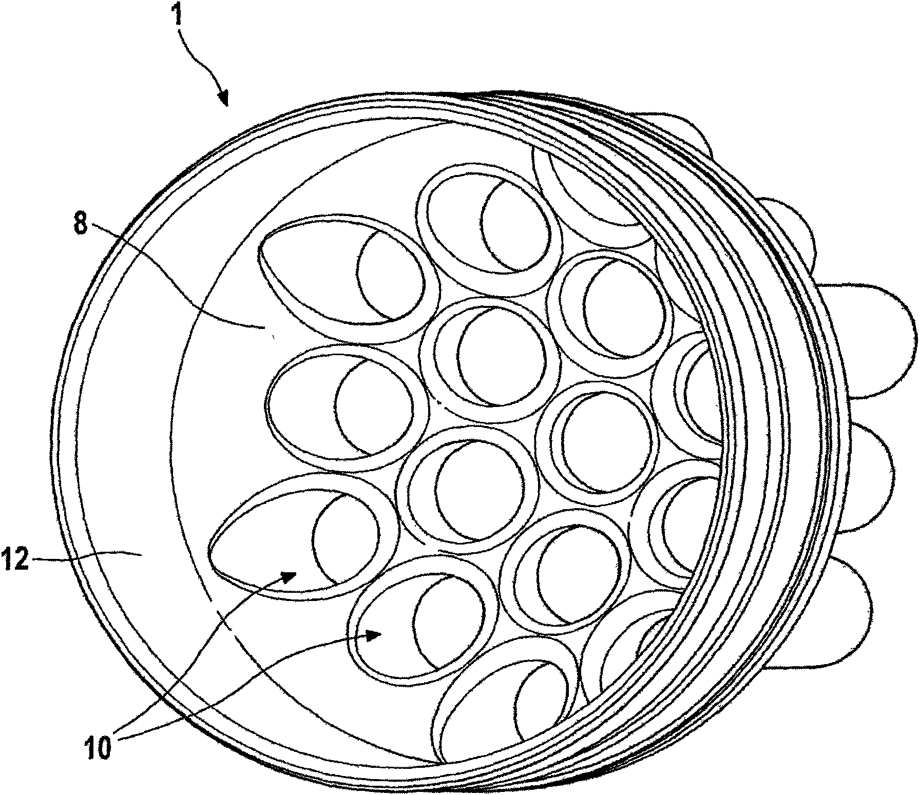
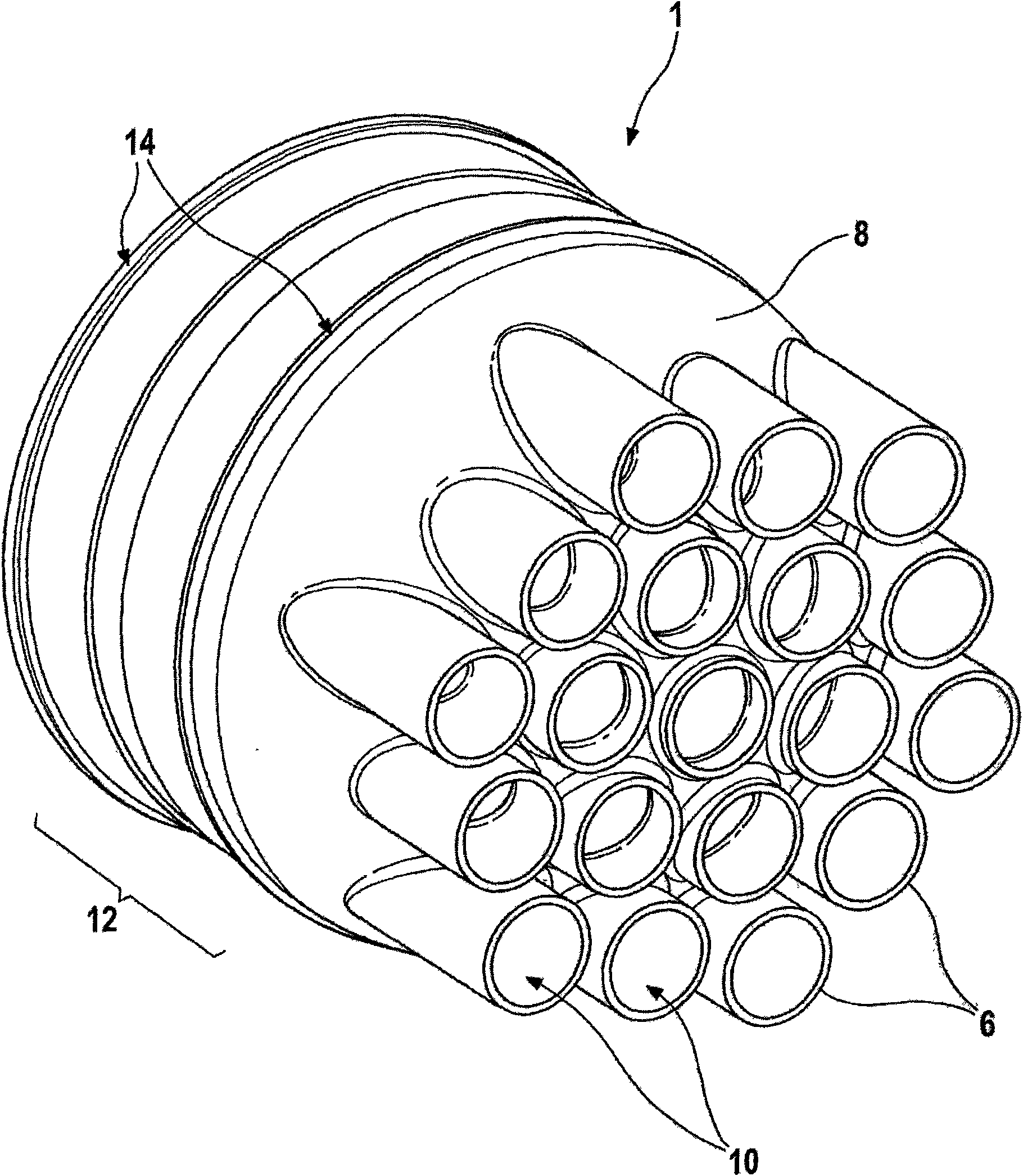
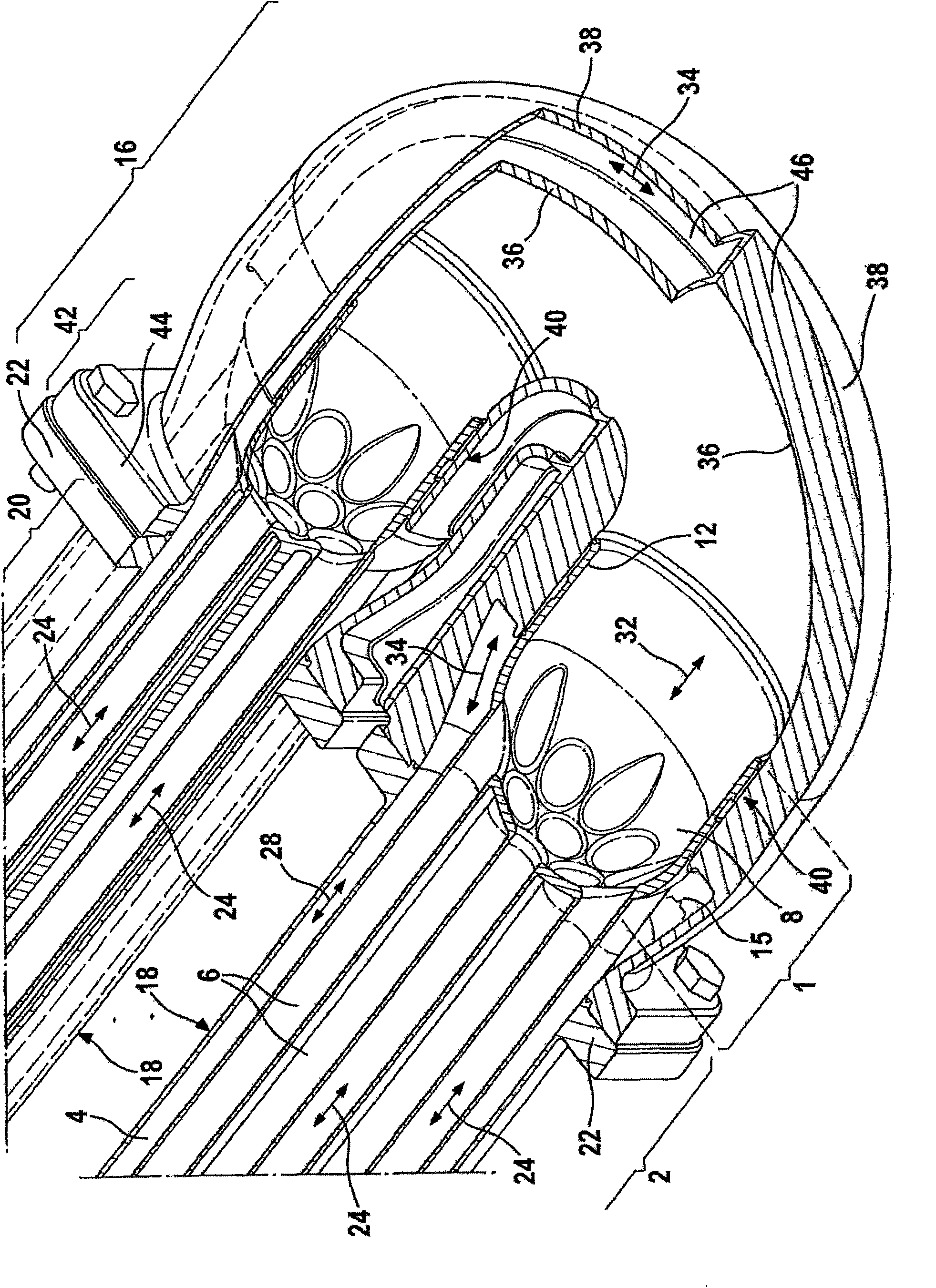
[0085] The end section 1 comprises a partial section 8 of substantially hemispherical configuration. On the peripheral surface of its outer appearance, the local section 8 is integrally connected to the heat transfer tube 6 of the tubular heat transfer device 2, the central axis of the hemisphere is oriented with the central axis of the tubular heat transfer device 2 or the heat transfer tube 6 respectively parallel. The end section 1 includes 19 through holes 10 corresponding in number and arrangement to the 19 heat transfer tubes 6 and in fluid communication with them. The through hole 10 has a substantially circular cross-section.

[0086] Inside the substantially hemispherical partial section 8 of the end section 1 of the tubular heat transfer device 2 , the inlet region of each through hole 10 has a circular shape.

[0087] The tip section 1 further comprises a substantially hollow cylindrical partial section 12 integrally connected to the hemispherical partial section ...


PUM


Abstract

The present invention relates to a pipe heat exchanger (2) for heat exchange between at least two food flows (26; 30), a dual deflection flanged bend (16) for the pipe heat exchanger, an adapter (56)and a system for the pipe heat exchanger. Furthermore, described is a method for transferring heat between at least two food flows (26, 30). The dual deflection flanged bend (16) includes two separated flow paths (32, 34), wherein a first food flow (26) may be transferred in the first flow path (32) of the dual deflection flanged bend (16); and the second food flow (30) may be transferred in the second flow path (34) of the dual deflection flanged bend (16). In addition, the heat may be transferred between the two flow paths (32, 34) of the dual deflection flanged bend (16).

Description

technical field [0001] The invention relates to a tubular heat transfer device for heat transfer between at least two food streams according to the preamble of claim 1, a tube heat transfer device for heat transfer between at least two food streams according to claim 6 A double return elbow of a tubular heat transfer device, a connector for a tubular heat transfer device for heat transfer between at least two food streams according to claim 13, a connector for heat transfer between at least two food streams according to claim 18 A system for heat transfer between at least two food streams, and a method for heat transfer between at least two food streams according to claim 21. Background technique [0002] In the food industry it is often necessary to remove heat from or supply heat to liquid food. For this purpose, for example, plate or tube heat transfer devices are often used. Parallel to the use of tubular heat transfer devices, heating or cooling media, or heat accumul...

Claims


Application Information

Patent Timeline
Patent Type & Authority Applications(China)
IPC IPC(8): F28D7/10F28F9/26
CPCF28D7/10F28D2021/0042A23C3/033F28F9/26F28D7/1607A23L3/22
Inventor 约翰·尤斯特尔
Owner KRONES AG
Why Eureka
Try Eureka