Plasma processing equipment, its radio frequency apparatus and radio frequency conveying method

A technology of radio frequency devices and processing equipment, applied in the field of microelectronics, can solve problems such as uneven plasma, uneven electromagnetic field, and differences in processing speed of plasma density workpieces, and achieve the effect of improving uniformity and eliminating differences in concentration

Inactive Publication Date: 2010-03-24
BEIJING NAURA MICROELECTRONICS EQUIP CO LTD
View PDF0 Cites 4 Cited by
  • Summary
  • Abstract
  • Description
  • Claims
  • Application Information

AI Technical Summary

Problems solved by technology

[0008] As we all know, in the radial direction of the reaction chamber 11, the electromagnetic field generated by the inductively coupled coil 14 is not uniform, which will cause the concentration of the plasma excited by it to appear inhomogeneous in the radial direction of the reaction chamber 11, and the plasma Other factors such as the specific structure of the processing equipment may also cause the plasma to not be uniformly distributed in the radial direction of the reaction chamber 11
The inhomogeneity of the plasma density will lead to differences in the processing rates of different parts of the workpiece 15, which will obviously have a significant adverse effect on the process
[0009] In the case that the size of the reaction chamber 11 is small and the process line of the workpiece 15 is large, the difference in plasma concentration in the radial direction of the reaction chamber 11 can still be alleviated to a certain extent through diffusion, and the process requirements can be met; however, with As the size of the reaction chamber 11 continues to increase, it has become more and more difficult to make the plasma density uniform through the diffusion effect, and as the process lines of the workpiece 15 gradually become smaller, the difference in plasma concentration will have an adverse effect on the process. more and more prominent

Method used


Image

  • Plasma processing equipment, its radio frequency apparatus and radio frequency conveying method
  • Plasma processing equipment, its radio frequency apparatus and radio frequency conveying method
  • Plasma processing equipment, its radio frequency apparatus and radio frequency conveying method

Examples


Embodiment Construction

[0032] In order to enable those skilled in the art to better understand the solution of the present invention, the present invention will be further described in detail below in conjunction with the accompanying drawings and specific embodiments.

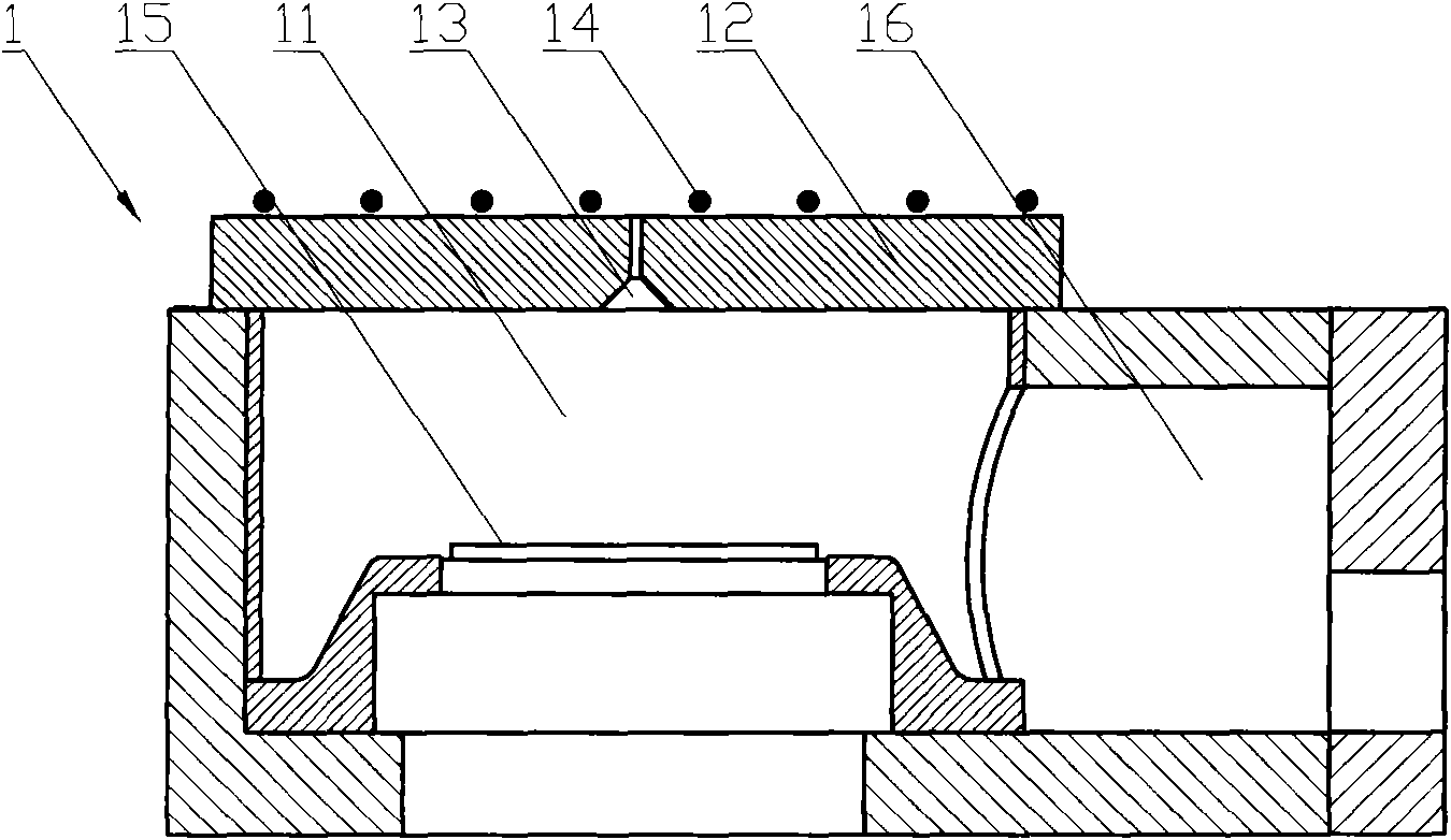
[0033] The radio frequency device for plasma processing equipment provided by the present invention includes a radio frequency power supply, a radio frequency matching device and an inductive coupling coil, and the three are connected in sequence.

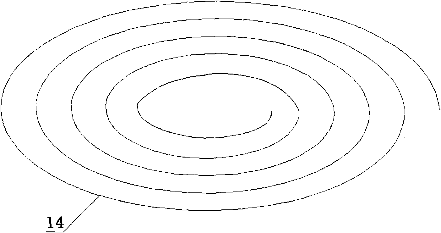
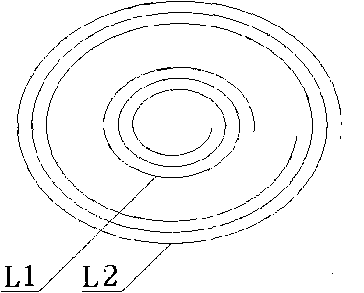
[0034] Please refer to image 3 , image 3 It is a structural schematic diagram of a specific embodiment of the inductively coupled coil provided by the present invention.

[0035] In the first specific implementation manner, the inductively coupled coil provided by the present invention includes at least two independent parts, that is, the central coil L1 and the peripheral coil L2.

[0036] The central coil L1 is located at the center of the top of the reaction chamber of the plasma ...


PUM


Abstract

The invention discloses a radio frequency apparatus, includes a radio frequency power supply, a radio frequency adapter and an inductance coupling coil connected in order, wherein the inductance coupling coil includes a center coil and at least a group of peripheral coils surrounding the center coi;l the center coil and the peripheral coils are in mutual independence, and the proportion of radio frequency current in these coils can be regulated. The invention also discloses a plasma processing equipment including the radio frequency apparatus. In the radio frequency conveying method disclosedby the invention, radio frequency energies are respectively input to the center position and peripheral position of the reaction chamber through at least two mutually independent inductance coupling coils, and the proportion of radio frequency current in these coils can be regulated according to the plasma concentration at these positions. As subarea conveying and subarea control of the radio frequency energy is realized, the uniformity of the plasma in the radial direction of the reaction chamber can be improved, thereby ensuring the smooth completion of the fine processing to the workpiece by the plasma processing equipment.

Description

technical field [0001] The invention relates to the technical field of microelectronics, in particular to a radio frequency device for plasma processing equipment. The present invention also relates to a plasma processing device comprising the above-mentioned radio frequency device, and a radio frequency delivery method for inputting radio frequency energy into a reaction chamber of the plasma processing device. Background technique [0002] Plasma processing equipment is widely used in the field of microelectronics technology. [0003] Please refer to figure 1 , figure 1 It is a schematic diagram of a typical plasma processing equipment. [0004] The plasma processing equipment 1 has a reaction chamber 11 inside, and the top of the reaction chamber 11 has an upper cover 12, and the upper cover 12 is usually a quartz cover. A gas inlet 13 is provided in the middle of the upper cover 12 so as to input gas into the reaction chamber 11 through the gas inlet 13 . The top of...

Claims


Application Information

Patent Timeline
Patent Type & Authority Applications(China)
IPC IPC(8): H05H1/46H01J37/32
Inventor 陈鹏
Owner BEIJING NAURA MICROELECTRONICS EQUIP CO LTD
Why Eureka
Try Eureka