Optical element driver, lens-barrel and exposure apparatus and method for fabricating device

A technology of optical components and driving devices, which is applied in the fields of optical components, semiconductor/solid-state device manufacturing, optics, etc., and can solve problems such as lens displacement and limitation

Inactive Publication Date: 2010-03-24
NIKON CORP
View PDF2 Cites 6 Cited by
  • Summary
  • Abstract
  • Description
  • Claims
  • Application Information

AI Technical Summary

Problems solved by technology

[0007] However, in the above-mentioned lens driving device, none of the above-mentioned three Z linear motors can displace the lens in a direction other than the direction of its optical axis.
Therefore, there is a problem that the composition of optical characteristics that can be corrected is limited

Method used


Image

  • Optical element driver, lens-barrel and exposure apparatus and method for fabricating device
  • Optical element driver, lens-barrel and exposure apparatus and method for fabricating device
  • Optical element driver, lens-barrel and exposure apparatus and method for fabricating device

Examples


no. 1 approach

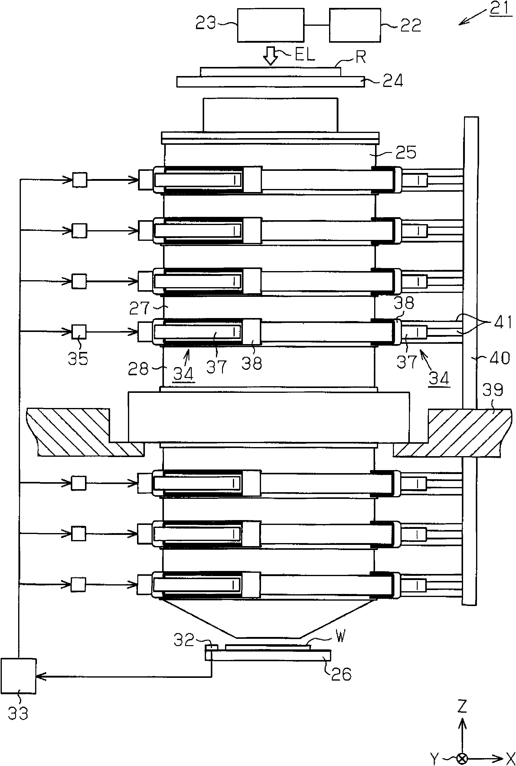
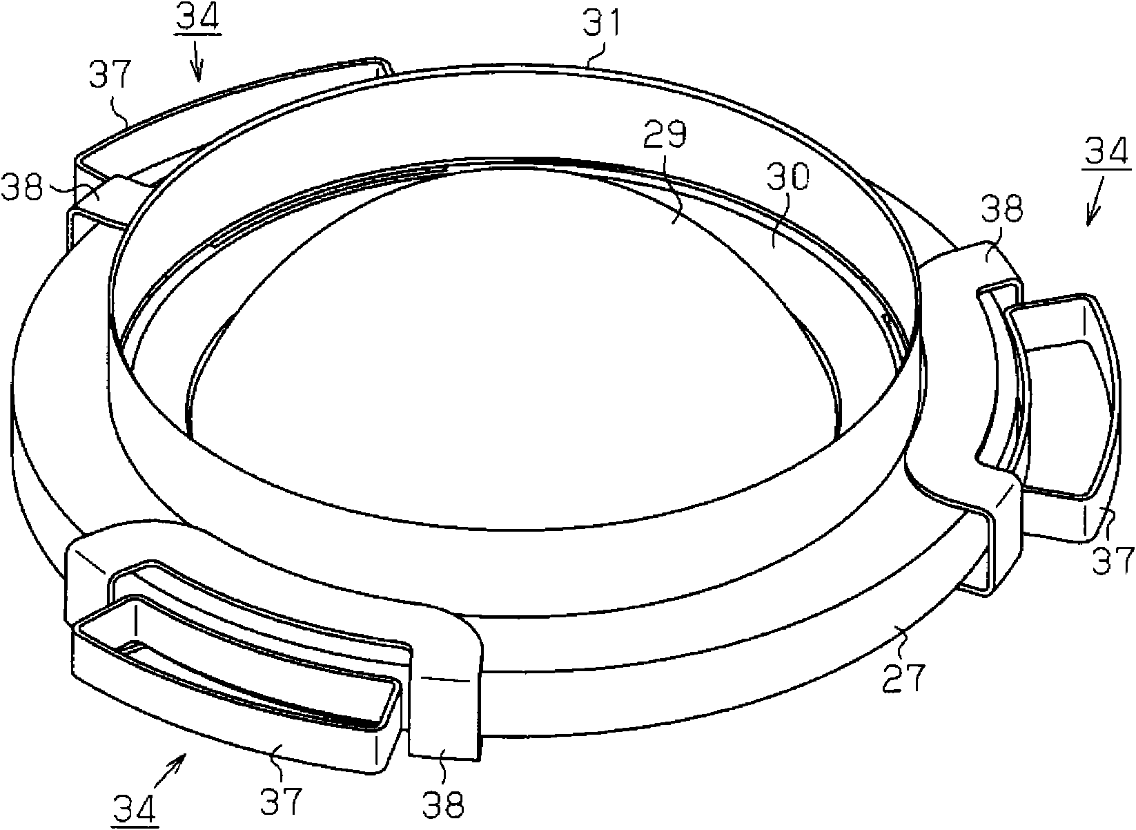
[0027] The following is based on Figure 1 to Figure 6 A first embodiment in which the exposure apparatus, optical element driving apparatus, and lens barrel of the present invention are embodied as, for example, an exposure apparatus for semiconductor element manufacturing, an optical element driving apparatus for driving optical elements, and a lens barrel for housing a projection optical system will be described.

[0028] figure 1 The schematic structure of the exposure apparatus 21 is shown. Such as figure 1 As shown, the exposure device 21 includes a light source 22, an illumination optical system 23, a master stage 24 holding a reticle R (which may also be a photomask), a projection optical system 25, and a wafer stage 26 holding a wafer W.

[0029] The light source 22 is, for example, an ArF excimer laser light source. The illumination optical system 23 includes various optical elements and an aperture diaphragm, wherein the various optical elements include optical...

no. 2 approach

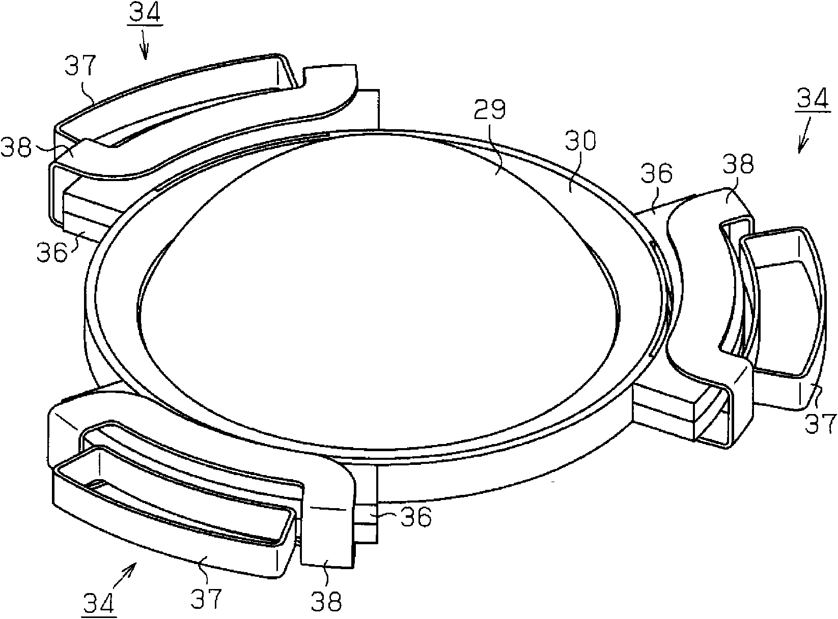
[0063] Next, centering on the parts different from those of the first embodiment, based on Figure 7 and Figure 8 The lens driving device 34 of the second embodiment will be described.

[0064] Such as Figure 7 and Figure 8As shown, the lens driving device 34 of the second embodiment includes a first driving unit 51 and a second driving unit 52 that drive the lens unit 30 in the direction of the optical axis, and the first driving unit 51 and the second driving unit 52 respectively include Closed field induction motor.

[0065] Such as Figure 7 As shown, the first driving part 51 has a permanent magnet 53 provided on the lens unit 30 . The north pole of the permanent magnet 53 faces the lens 29 side, that is, the inside of the lens unit 30 . The south pole of the permanent magnet 53 faces the outside of the lens unit 30 . The permanent magnet 53 is covered by the cover 31 similarly to the first embodiment. Magnetic conduction path 54 having a U-shaped cross section...


PUM


Abstract

The invention provides an optical element driver, a lens-barrel, an exposure apparatus and a method for fabricating device. Permanent magnets (36), which are bonded together in such a manner that theN poles face each other and the S poles are exposed, are secured to the outer circumferential edge of a lens cell (30). A first drive coil (37) is so arranged as to face the outlet of the magnetic line of force from the bonded surfaces of the N poles of the permanent magnets (36), and a second drive coil (38) is so arranged as to face the inlet of the magnetic line of force to the permanent magnets (36). Posture of a lens (29) is adjusted by regulating the current applied to the first drive coil (37) and the second drive coil (38) and driving the lens cell (30) in the direction of the opticalaxis and in the horizontal direction in a state floating from a cover (31).

Description

technical field [0001] The present invention relates to an optical element driving device for driving an optical element such as a lens or a mirror. Furthermore, the invention relates to a lens barrel having at least one optical element. Furthermore, this invention relates to the exposure apparatus used for the manufacturing process of devices, such as a semiconductor element, a liquid crystal display element, or a thin-film magnetic head, and the manufacturing method of the said device, for example. Background technique [0002] This application claims priority based on Japanese Patent Application No. 2007-126928 for which it applied on May 11, 2007, and uses the content here. [0003] The optical system in such an exposure apparatus includes optical elements such as lenses and mirrors, and the optical elements are held by an optical element holding device. Furthermore, among the optical systems included in the exposure apparatus, the projection optical system is configur...

Claims


Application Information

Patent Timeline
Patent Type & Authority Applications(China)
IPC IPC(8): G02B7/02H01L21/027
CPCG02B7/02G02B7/023G02B26/0816G02B7/1828G02B7/1821G03F7/70825G03F7/70008G03F7/70316G02B7/04
Inventor 新井洋一
Owner NIKON CORP
Why Eureka
Try Eureka