Method and apparatus for determining differential group delay and polarization mode dispersion

A polarization and polarization-related technology, applied in the structure of optical resonator cavity, testing of machine/structural components, structure/shape of active medium, etc., can solve the wrong estimation, reduce the maximum measurable PMD value, limit the maximum measurable length And other issues

Active Publication Date: 2010-03-31
EXFO
View PDF10 Cites 23 Cited by
  • Summary
  • Abstract
  • Description
  • Claims
  • Application Information

AI Technical Summary

Problems solved by technology

It is worth noting that correct measurement of modern "spun fibers" already requires assumptions to be made about their performance and is therefore unacceptable for commercial instruments
[0035] A second example is that birefringence and other parameters must be measured accurately over the entire length - even in those segments of the fiber where the local properties do not satisfy the assumed model and conditions; otherwise, the derived The PMD of , which is an integral over some long length, can still be largely misestimated, even qualitatively
It can also be reduced by increasing the equivalent laser linewidth, i.e. the intrinsic laser linewidth, etc., or by using "dithering" or averaging the traces over wavelength, but this reduces the maximum measurable PMD value, and thus may also limit the maximum measurable length, since PMD increases with length

Method used


Image

  • Method and apparatus for determining differential group delay and polarization mode dispersion
  • Method and apparatus for determining differential group delay and polarization mode dispersion
  • Method and apparatus for determining differential group delay and polarization mode dispersion

Examples


Embodiment Construction

[0147] In the figures, identical or similar components bear the same reference numerals in different figures, where appropriate with a symbol indicating differences.

[0148] The various aspects of the invention, as well as their respective implementations, are based on the same underlying theory. The embodiment of these aspects can advantageously be used for: for narrow optical channel or in specified broad wavelength range, to PMD or depend on the double-ended measurement of the DGD of wavelength, single-ended overall PMD measurement, single-ended cumulative PMD measurement and Other related variants.

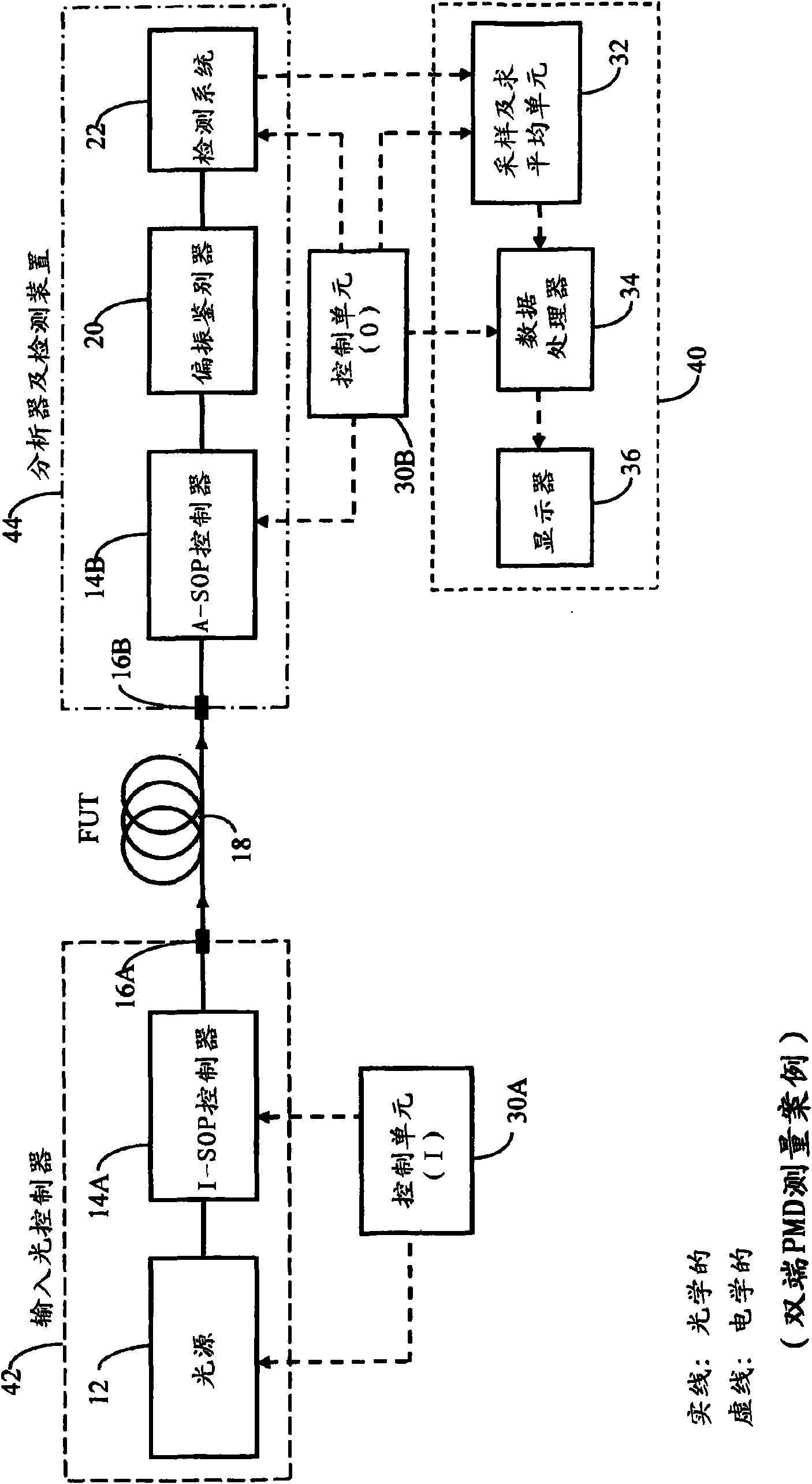
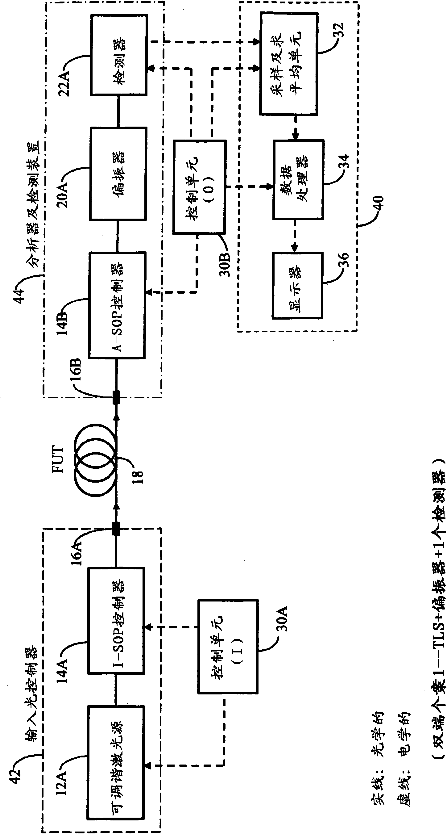
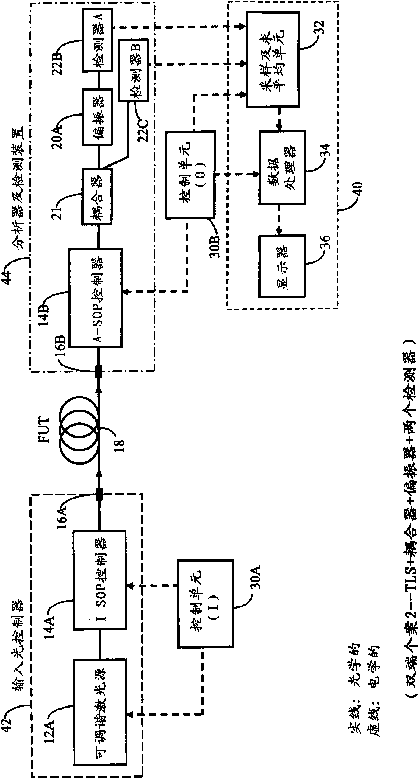
[0149] In each of the preferred embodiments of the invention described below, there will generally be three main parts, namely (i) an input light controller, (ii) an analyzer or detection unit, and (iii) an analog and digital processing unit, along with One or more control units. In the so-called double-ended case, the input light controller will be located at the near end ...


PUM


Abstract

A method and apparatus for measuring at least one polarization-related characteristic of an optical path (FUT) uses a light input unit connected to the FUT at or adjacent a proximal end of the FUT anda light output unit connected to the FUT at or adjacent its proximal or distal end. The light input unit injects into the FUT at least partially polarized light having a controlled state of polarization (I-SOP). The output light unit extracts corresponding light from the FUT, analyzes and detects the extracted light corresponding to at least one transmission axis (A-SOP), and processes the corresponding electrical signal to obtain transmitted coherent optical power at each wavelength of light in each of at least two groups of wavelengths, wherein the lowermost (lambda 1) and uppermost (lambdau) said wavelengths in each said group of wavelengths are closely- spaced. A processing unit than computes at least one difference in a measured power parameter corresponding to each wavelength in awavelength pair for each of the at least two groups, the measured power parameter being proportional to the power of the said analyzed and subsequently detected light, thereby defining a set of at least two measured power parameter differences; computes the mean-square value of said set of differences; and calculating the at least one polarization-related FUT characteristic as at least one predetermined function of said mean-square value, the predetermined function being dependent upon the small optical frequency difference between the wavelengths corresponding to the said each at least said two pairs of closely-spaced wavelengths.

Description

[0001] Cross-references to related literature [0002] This application claims priority to US Provisional Patent Application No. 60 / 907,313, filed March 28, 2007, and US Continuation-in-Part Application No. 11 / 727,759, filed March 28, 2007. The entire contents of these two patent applications are hereby incorporated by reference into the text of this patent application. technical field [0003] The present invention relates to methods and facilities for measuring the polarization-dependent properties of an optical path, and the invention is particularly suitable for measuring the differential group delay (DGD) of an optical path at a specific wavelength or the root-mean-square DGD or average DGD within a specified wavelength interval , the optical path mainly includes an optical waveguide, such as an optical fiber link. When the specified wavelength interval is wide enough, the root mean square DGD or average DGD measurement results are very close to the polarization mode dis...

Claims


Application Information

Patent Timeline
Patent Type & Authority Applications(China)
IPC IPC(8): G01M11/02H01S3/067H01S3/082H01S3/23H01S5/026H01S5/10
CPCG01M11/336G01M11/335
Inventor N·西尔陈洪新
Owner EXFO
Why Eureka
Try Eureka