
Hot extrusion forming process of half-shaft casings and special device

A half-shaft sleeve, forming process technology, applied in forging/pressing/hammer devices, manufacturing tools, metal processing equipment, etc., can solve the problem of high mold replacement cost, unstable workpiece coaxiality, short life of forging molds, etc. problems, to ensure the lubrication and cooling time, reduce the artificial machining allowance, and achieve the effect of stable coaxiality of the workpiece

Inactive Publication Date: 2010-04-07
济南中森机械制造有限公司
View PDF0 Cites 38 Cited by
  • Summary
  • Abstract
  • Description
  • Claims
  • Application Information

AI Technical Summary

Problems solved by technology

[0003] 1. Only the forging shape is relatively simple, and the products produced are relatively single. Because the forging die generally has a short life, although the operation is simple and the one-time investment is small, the efficiency is low. In order to ensure that the forging die has sufficient cooling and lubrication, there must be work intervals Time, manual operation takes about 180S to complete a workpiece;
[0004]2. The deformation of the mold is large after long-term work, and the inner hole of the workpiece is deflected, resulting in poor coaxiality between the inside and the outside; It is completed on two devices together, resulting in increased cost
[0005]3. The material quota is large. Due to the instability of the coaxiality of the workpiece, in order to ensure the machining, the machining allowance is artificially increased
[0006]4. It is not suitable for long-term mass production, and the cost of mold replacement caused by cooling is too high, which undoubtedly greatly increases the production cost of the company

Method used


Image

  • Hot extrusion forming process of half-shaft casings and special device
  • Hot extrusion forming process of half-shaft casings and special device
  • Hot extrusion forming process of half-shaft casings and special device

Examples


Embodiment Construction

[0036] The present invention will be described in further detail below in conjunction with the accompanying drawings and specific embodiments. The following description is only exemplary and does not limit the protection scope of the present invention.

[0037] A hot extrusion forming process for a half-shaft casing, comprising the following steps:

[0038] 1) Select the appropriate round steel according to the design product, and heat the round steel to 1100-1250 ° C. Considering the rapid heating, preventing the oxidation of the round steel after heating and reducing material loss, the heating device is an intermediate frequency diathermy furnace;

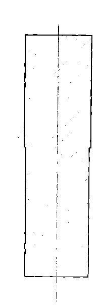
[0039] 2) Forward extrusion upsetting: Put the above-mentioned heated round steel into the upsetting mold to form upsetting into a forming blank whose shape is suitable for the side wall of the pre-forging mold cavity, such as image 3 As shown, the diameter of the forming blank meets the design requirements, and the length is 60...


PUM


Abstract

The invention discloses a hot extrusion forming process of half-shaft casings, comprising the following steps: 1) selecting proper round steel according to design products and heating the round steel to 1100-1250 DEG C, 2) carrying out forward extrusion and upsetting, 3) carrying out backward extrusion and positioning, 4) carrying out shallow punching and performing, and 5) carrying out deep punching, finish forging and forming. The invention also discloses a special device for implementing the hot extrusion forming process, comprising upsetting tools, positioning tools, tools for shallow punching and performing and tools for deep punching, finish forging and forming, which are arranged from left to right in sequence. The process has four stations. Each station has enough cooling and lubricating time. Not only can the special device not be deformed after long-term use and the workpieces can not have the problem that inner hole inclination leads to inner and outer coaxiality difference, but also the special device is protected to reduce damage while the capacity is increased.

Description

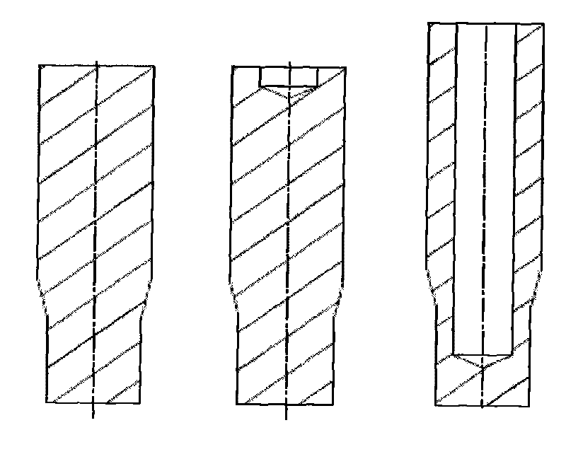
(1) Technical field [0001] The invention relates to a hot extrusion forming process and a special device for a half-shaft casing, belonging to the field of metal plastic deformation. (2) Background technology [0002] For a long time, the hydraulic press forging process has been using the traditional method, also considering the particularity of the hydraulic press, that is, setting a station in the hydraulic press and hot extrusion in 2-3 times, such as figure 1 Shown is the hot extrusion forging rough map of our company's shaft head products, the forging process is as follows figure 2 , that is, the conventional hot extrusion forging process method is adopted: the round steel is heated and placed into the mold for upsetting, pre-extrusion, and forming, and it is completed on a pair of molds. It has the following disadvantages: [0003] 1. Only the forging shape is relatively simple, and the products produced are relatively single. Because the forging die generally has a ...

Claims


Application Information

Patent Timeline
IPC IPC(8): B21J5/06B21J5/08B21J5/10B21J1/06B21J13/02
Inventor 崔健崔若平胡圣华
Owner 济南中森机械制造有限公司
Learn More