Method and device for emitting and receiving symmetrically-distributed light beams of laser radar

A beam emission and lidar technology, applied in the fields of lidar and environmental science, can solve the problems of different beam divergence angles, difficult to achieve coaxial transmission and reception optical system, unable to ensure the same overlap correction coefficient, etc., to achieve the effect of ensuring comparability

Active Publication Date: 2010-04-07
ANHUI INST OF OPTICS & FINE MECHANICS - CHINESE ACAD OF SCI
View PDF0 Cites 19 Cited by
  • Summary
  • Abstract
  • Description
  • Claims
  • Application Information

AI Technical Summary

Problems solved by technology

[0003] At present, for multi-wavelength lidar, one beam output device is used to emit multiple laser wavelengths into the atmosphere (multiple laser wavelengths are emitted by one laser or integrated into one beam after being emitted by multiple lasers), due to the refractive index and Different divergence angles, multiple laser wavelengths output by a laser also have different beam divergence angles, and laser beams of different wavelengths cannot be truly coaxial, that is, the different refractive indices of the optical output lens for different laser wavelengths cause separation of laser beams over long distances
Therefore, for the transmitting and receiving optical systems, it is not possible to realize the coaxiality of the transmitting and receiving optical systems in the true sense.
[0004] Whether it is a laser radar with a coaxial transmitting beam and a receiving beam or an off-axis laser radar with a transmitting beam and a receiving beam, it is difficult to realize the coaxiality of the transmitting and receiving optical system by using the same beam transmitting device for a multi-wavelength laser radar.
[0005] In order to carry out data comparison and joint analysis, the data is required to be comparable. Due to the difference in the refractive index and divergence angle of different laser wavelengths, in the case of the same beam output, the transceiver optical system will have different overlap correction coefficients. Therefore, the emission of a single beam cannot guarantee that the overlapping correction coefficients of the system at different laser wavelengths are the same or that the emission beams of multiple laser wavelengths cannot be truly parallel to the optical axis of the receiving optical system; The correction coefficient can only be approximated as the calculation result at a certain wavelength for data comparison and result analysis

Method used


Image

  • Method and device for emitting and receiving symmetrically-distributed light beams of laser radar
  • Method and device for emitting and receiving symmetrically-distributed light beams of laser radar
  • Method and device for emitting and receiving symmetrically-distributed light beams of laser radar

Examples


Embodiment Construction

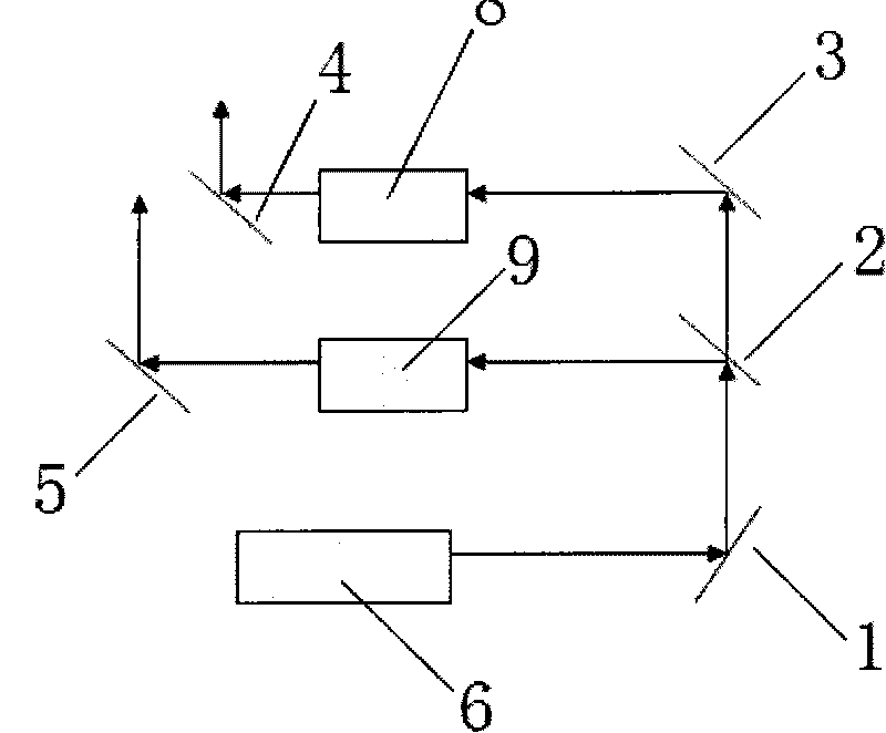
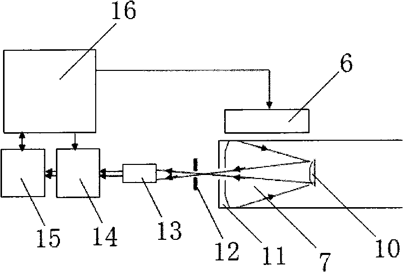
[0020] see figure 1 , a laser radar symmetrical distributed beam transmitting and receiving device, including a laser transmitting system, a laser receiving system, and a control, acquisition, processing and display system, the laser transmitting system includes a laser 6, the laser receiving system includes a telescope 7, and the front of the laser 6 There is a reflector 1, the laser emitted by the laser 6 is reflected by the reflector 1, reflected by the reflector 2 to the 355nm laser, and transmitted to the 1064nm and 532nm laser; after the 355nm laser is reflected, it is expanded by the second beam expander system 9 Reflected from the reflector 5 to the atmosphere; the transmitted 532nm laser is reflected by the reflector 3, and then expanded by the first beam expander system 8 and reflected from the reflector 4 to the atmosphere; the transmitted 1064nm laser is transmitted through the reflector 3; the reflector 2 , 3, 4, and 5 are arranged in parallel with each other, and...


PUM


Abstract

The invention discloses a method and a device for emitting and receiving symmetrically-distributed light beams of laser radar. A system adopts the method for independently emitting and receiving the light beams with a plurality of wavelengths, thereby eliminating an effect on a measurement result caused by different divergent angles and refractive indexes of the laser beams with the different wavelengths, independently realizing the calculation of the overlap coefficient of the system under the different laser wavelengths, developing the real coaxiality or completely parallel optical axes of receiving and emitting optical systems, ensuring data comparability and providing the method for the further development and practical application of the laser radar. The independent emission of the light beams with the different laser wavelengths in the system can be debugged under a visible software interface, so that an ordinary operator can finish the operation and maintenance of the system without the help of a precise measuring instrument or special technical personnel.

Description

technical field [0001] The invention relates to the fields of environmental science and laser radar technology, in particular to a laser radar symmetrical distributed beam transmitting and receiving method and device. Background technique [0002] Lidar is one of the rapidly developing high-tech, and it is the product of the combination of traditional radar technology and modern laser technology. Lidar emits laser pulses into the atmosphere, and conducts measurement and research on atmospheric optical characteristics and the temporal and spatial distribution of pollutants by receiving backscattered echo information after the interaction between atmospheric molecules or aerosol particles and lasers, and analyzes atmospheric visibility, aerosol Spatial and temporal distribution and variation of particulate matter, cloud base height, boundary layer height, characteristics of aerosol particles, and spatial distribution characteristics of water vapor and ozone. [0003] At prese...

Claims


Application Information

Patent Timeline
Patent Type & Authority Applications(China)
IPC IPC(8): G01S7/483G01S7/497
Inventor 赵南京刘建国刘文清陆亦怀张玉钧刘诚董云升张天舒赵雪松谢品华司福祺
Owner ANHUI INST OF OPTICS & FINE MECHANICS - CHINESE ACAD OF SCI
Why Eureka
Try Eureka