
Semiconductor laser all-fiber frequency stabilizing system

A laser and semiconductor technology, applied in semiconductor lasers, lasers, laser parts and other directions, can solve the problems of limited spectral line coverage, high cost of use, and reduced vacuum container effect, and achieve convenient, simple and stable integration, reduced loss, The effect of enhancing anti-interference ability

Inactive Publication Date: 2010-04-14
BEIHANG UNIV
View PDF0 Cites 14 Cited by
  • Summary
  • Abstract
  • Description
  • Claims
  • Application Information

AI Technical Summary

Problems solved by technology

[0003] At present, the existing laser frequency stabilization methods include: using the gain curve as a standard to stabilize the laser frequency, but it is difficult to achieve a high degree of stability; using the Zeeman effect or the Stark effect to stabilize the laser frequency, the stability can reach 10 -9 ; The laser frequency is stabilized by using atomic and molecular absorption lines, and the frequency stability is as high as 10 -13 □10 -14 , but the coverage of the spectral line is limited, it is difficult to find two suitable spectral lines for the two endpoints of the stable frequency sweep; using the sideband frequency locking technology to lock the frequency, using the Fabry-Perot resonant cavity as the standard frequency, the advantage is that it does not Limited by the band, and the Fabry-Perot resonator can achieve very high precision, the disadvantage is that the Fabry-Perot resonator must be placed in a vacuum container to reduce the influence of temperature, sound, and vibration, which makes it The weight is heavy, the cost of use is high, and the effect of the vacuum container is easy to decline with the extension of time; in addition, the Fabry-Perot resonator is very sensitive to vibration, and the satellite is subject to huge vibration and acceleration during launch. Affects the accuracy of the Fabry-Perot resonator

Method used


Image

  • Semiconductor laser all-fiber frequency stabilizing system
  • Semiconductor laser all-fiber frequency stabilizing system

Examples


Embodiment Construction

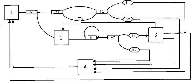
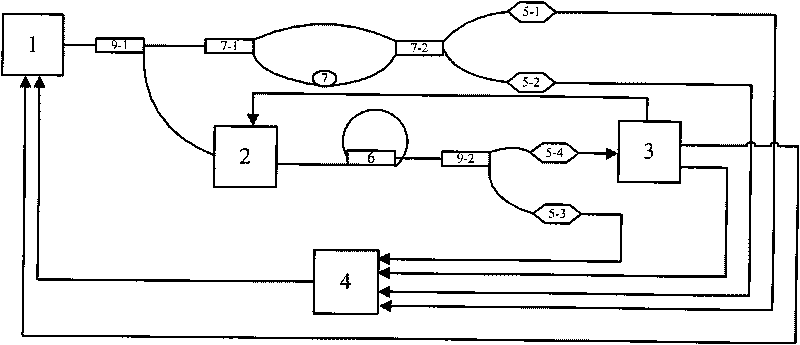
[0015] figure 1 It is a block diagram of a semiconductor laser all-fiber frequency stabilization system. The laser light emitted by a frequency-tunable external cavity semiconductor laser (1) is first divided into two beams by a 1×2 directional polarization-maintaining fiber coupler (9-1). One of them enters the optical fiber reference interferometer (7), which is used to monitor the change of the laser frequency. It first divides the laser into two beams by a 3dB 1×2 directional polarization-maintaining fiber coupler, and then passes through two single-mode polarization-maintaining After the polarized fiber enters the 3dB 2×2 directional polarization-maintaining fiber coupler for interference output, the intensity of the two beams formed are: P 1 =P 0 {1-cos[φ(v)+x]}, P 2 =P 0 {1+cos[φ(v)+x]}, converted into electrical signals by photodetectors (5-1) and (5-2) and then entered into DSP (4) for phase unwrapping processing to calculate the change of laser frequency , and th...


PUM


Abstract

The invention discloses a semiconductor laser all-fiber frequency stabilizing system, which belongs to the field of laser frequency-sweeping interferometery. The frequency stabilizing system consists of a non-mode-hopping frequency scanning semiconductor laser, an all-fiber reference interferometer, a high-finesse fiber ring resonator and a data acquisition processing and controlling system. In the semiconductor laser all-fiber frequency stabilizing system, the all-fiber reference interferometer is used for monitoring frequency changes of an external-cavity semiconductor laser, and frequency of the laser is stabilized to be equal to resonance frequency of the fiber ring resonator by using a feed back method when the laser frequency approaches resonance frequency of the fiber ring resonator after scanning. The semiconductor laser all-fiber frequency stabilizing system has the advantages of small volume, light weight, high precision and fine stabilizing degree and is adaptable to laser frequency-sweeping interferometering systems.

Description

technical field [0001] The present invention is a semiconductor laser frequency stabilization system based on optical fiber and optical fiber devices, which mainly uses the Pound-Drever-Hall frequency stabilization technology based on the change of the transmitted light field of the optical fiber ring cavity, and combines the reference interferometer to monitor the frequency scanning of the laser. to achieve frequency stabilization. This technology is mainly used in the field of high-precision laser interferometry. Background technique [0002] In recent years, using the interference characteristics of lasers to measure high-precision absolute distances has become a research hotspot, the most common of which are Frequency Scanning Interferometry (FSI) and Frequency Modulated Continuous Wave (FMCW). Among them, the frequency scanning method uses the phase change of the interference fringe formed by the continuous scanning of the laser frequency to complete the laser ranging....

Claims


Application Information

Patent Timeline
IPC IPC(8): H01S5/00H01S5/0687
Inventor 江月松邓士光
Owner BEIHANG UNIV
Learn More