High-precision low-voltage voltage/current switching circuit

A technology of voltage-current conversion and voltage-following circuit, which is applied in the direction of output power conversion device, DC power input conversion to DC power output, electrical components, etc. It can solve the problems of inaccurate restoration of output voltage and low mirror image precision, and achieve The effect of good output current matching, low working voltage and strong suppression ability

Active Publication Date: 2010-04-14
MAXIC TECHNOLOGY CORPORATION
View PDF0 Cites 12 Cited by
  • Summary
  • Abstract
  • Description
  • Claims
  • Application Information

AI Technical Summary

Problems solved by technology

The voltage-to-current conversion circuit has low current mirror

Method used


Image

  • High-precision low-voltage voltage/current switching circuit
  • High-precision low-voltage voltage/current switching circuit
  • High-precision low-voltage voltage/current switching circuit

Examples


Example Embodiment

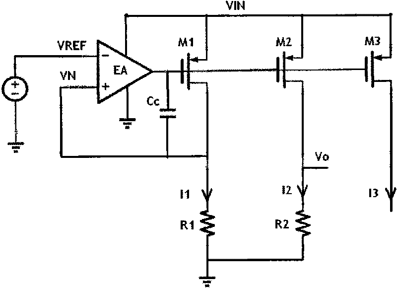
[0028] Figure 4 It is a schematic diagram of a PMOS voltage-to-current conversion circuit. Figure 4 Among them, the PMOS transistors M1, M2, and M3 form a current mirror and are connected to the input voltage VIN. The reference voltage source generates a reference voltage VREF, and inputs the reference voltage VREF as an input signal to the inverting terminal of the error amplifier EA, and the output terminal of the error amplifier EA drives the current mirror to generate mirror currents and output them respectively. The voltage follower circuit includes a first branch, a second branch and a third branch. The first end (point A) of the first branch is connected to the drain of M1, and the first end (point B) of the second branch is connected to the drain of M1. The drain of M2 is connected, and the first end (point C) of the third branch is connected to the drain of M3; and the voltage follower circuit is used to make the drain voltage of M2 and the drain voltage of M3 conn...


PUM


Abstract

The invention relates to a high-precision low-voltage voltage/current switching circuit. The circuit comprises a current mirror, a voltage following circuit, an error amplifier and a first resistor, wherein the current mirror comprises a first transistor and a third transistor, the first end of the first transistor and the first end of the third transistor are connected with input voltage, and the second end of the first transistor and the second end of the third transistor are respectively connected with the voltage following circuit; the voltage following circuit is used for enabling the voltages of the second end of the first transistor and the second end of the third transistor, which are connected with the voltage following circuit, to be equal; the first input end of the error amplifier receives reference voltage, and the second input end of the error amplifier is connected to the voltage following circuit; and the first resistor is connected with the second input end of the error amplifier so as to obtain first current and then copies the first current to obtain output current. In the invention, the voltage/current switching circuit has low working voltage, strong power source change inhibiting ability as well as simple and reliable circuit structure so that the invention is widely applied to analog integrated circuits.

Description

technical field [0001] The invention relates to an analog integrated circuit, in particular to a voltage-current conversion circuit. Background technique [0002] In integrated circuit systems, the mutual conversion between voltage and current is very common. For example, in a digital-analog hybrid circuit or in a power management circuit, an accurate reference voltage can provide an accurate reference to the ground for the entire system. The system's overvoltage protection, overcurrent protection, overheat protection, error amplifier, and comparator all need a Accurate reference points, but in a system full of noise, if the voltage signal is directly transmitted from the reference source to the required module, it will be easily disturbed by parasitic parameters such as layout and wiring. Slight interference will lead to system performance degradation. Severe disturbances are likely to cause malfunction of the system. Therefore, by converting the reference voltage into a ...

Claims


Application Information

Patent Timeline
IPC IPC(8): H02M3/156
Inventor 郑儒富
Owner MAXIC TECHNOLOGY CORPORATION
Why Eureka
Try Eureka