
Cathode contact for mandril of pull coating machine

A cathode joint and mandrel technology, applied in electrodes and other directions, can solve the problems of not meeting the needs of modern industrial production, affecting the efficiency and quality of electroplating, and low current density of mandrels, so as to improve the efficiency and quality of electroplating and enhance the current density. and electric field strength, the effect of meeting the requirements of electroplating

Inactive Publication Date: 2011-03-23
天津滨海龙泰科技发展有限公司
View PDF0 Cites 0 Cited by
  • Summary
  • Abstract
  • Description
  • Claims
  • Application Information

AI Technical Summary

Problems solved by technology

Since the front end of the mandrel has a frustum-shaped structure, and the bolt hole occupies a large area, the area of ​​its contact surface with the cathode circular plate is small, which reduces its electrical conductivity, resulting in a small current density of the mandrel, which affects the electroplating process. High efficiency and quality, prolonging the plating time
[0004] In addition, the existing mandrel electroplating is intermittently electroplated one by one, and the existing electroplating cathode joint can only be applied to one mandrel, the production efficiency is low, and it cannot meet the needs of modern industrial production

Method used


Image

  • Cathode contact for mandril of pull coating machine
  • Cathode contact for mandril of pull coating machine
  • Cathode contact for mandril of pull coating machine

Examples


Embodiment Construction

[0019] The embodiments of the present invention will be further described below in conjunction with the accompanying drawings; it should be noted that: this embodiment is descriptive, not restrictive, and cannot be used to limit the protection scope of the present invention.

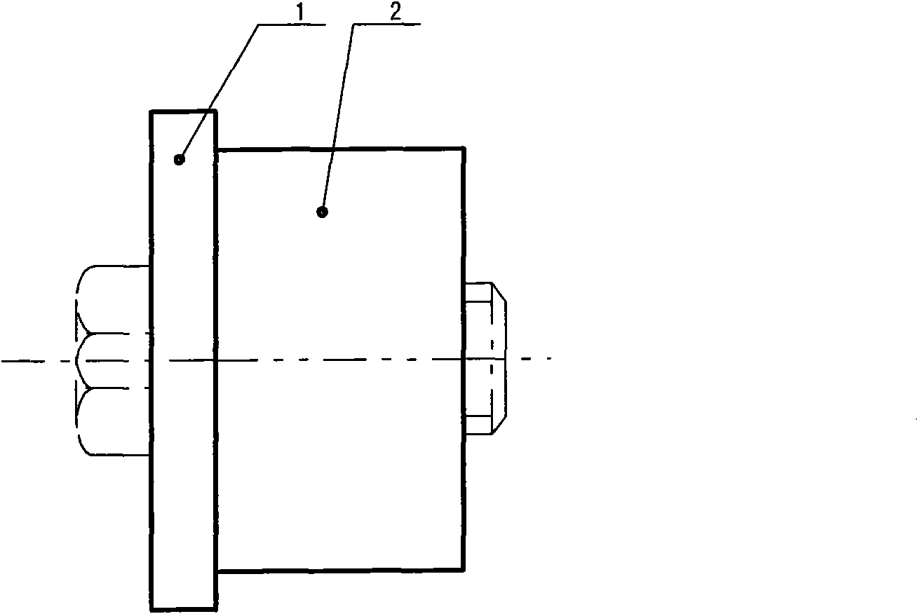
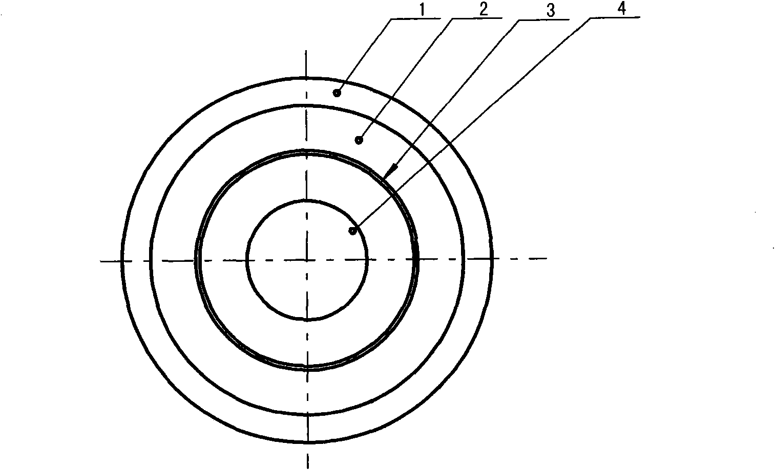
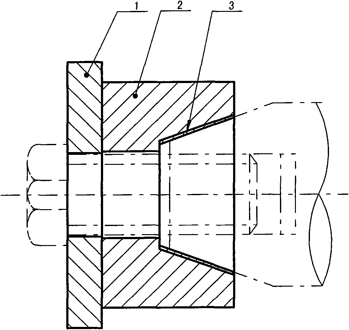
[0020] A drawing and plating mandrel rod cathode joint, including a cathode disc 1, the cathode disc is connected to the cathode power supply, and a bolt (shown by a dotted line) is inserted in the central shaft hole 4 made by the cathode disc, and the bolts are engaged to connect the coaxial mandrel (shown in dotted line). The innovation point of the present invention is:

[0021] 1. An electrode sleeve 2 is coaxially installed between the cathode disk and the mandrel. The middle part of the electrode sleeve is made with a tapered groove matching the mandrel conical surface to realize the formation of the tapered groove and the mandrel conical surface. surface contact. In order to improve the contact ...


PUM


Abstract

The invention relates to a cathode contact for a mandril of a pull coating machine, comprising a cathode disk, wherein the cathode disk is connected with a cathode power, and a threaded bolt penetrates through a middle axle hole formed in the cathode disk and is in meshed connection with a coaxial mandril; and an electrode sleeve is coaxially installed between the cathode disk and the mandril, a cone tank matched with the conical surface of the mandril is formed in the middle of the electrode sleeve, and the cathode disk, the mandril and the electrode sleeve are coaxially installed by the threaded bolt. The cathode contact has simple integral structure and scientific and reasonable design, solves problems occurring in the electroplating production of the mandril, enhances the current density and the electric intensity of electroplating, increases the production efficiency of electroplating and can perfectly meet the requirement on electroplating of the mandril.

Description

technical field [0001] The invention belongs to the field of electroplating treatment, in particular to a cathode joint of a drawing and plating core rod. Background technique [0002] The mandrel is a deformation tool in the production of seamless steel pipes. It is long and works under extremely harsh conditions such as high temperature, high pressure, and high speed. Therefore, it requires high technical conditions for mandrel processing. The chromium plating on the surface of the mandrel is to improve the wear resistance of the mandrel during use. At the same time, it is required that the chromium layer on the surface of the mandrel should not deform or fall off under the action of thermal stress and compressive stress. Higher requirements. At present, the electroplating of the mandrel still adopts the traditional cathode and anode method. The cathode is connected to the mandrel, and the anode is connected to the electroplating tank. The negative and positive ions in th...

Claims


Application Information

Patent Timeline
Patent Type & Authority Patents(China)
IPC IPC(8): C25D17/10C25D7/00
Inventor 黄平
Owner 天津滨海龙泰科技发展有限公司
Learn More