Automatic wielding mechanical device for forming machine of numerical control reinforcing cage

A steel cage forming machine, automatic welding technology, applied in auxiliary devices, welding equipment, auxiliary welding equipment and other directions, can solve the problems affecting the production efficiency and quality of steel cages, labor intensity of many personnel, irregular welding point forming, etc. The effect of saving manpower, improving welding quality and reducing labor intensity

Active Publication Date: 2010-05-05
TJK MACHINERY TIANJIN
View PDF0 Cites 44 Cited by
  • Summary
  • Abstract
  • Description
  • Claims
  • Application Information

AI Technical Summary

Problems solved by technology

[0003] To sum up, steel cages are more and more widely used in pile foundation construction, while traditional steel cages are mostly made by hand, which not only requires a large number of personnel, but also has high labor intensity, low work efficiency and high cost; the other part The traditional steel cage manufacturing equipment is used for production. This traditional steel cage production equipment has a low degree of automation. Although the production efficiency is improved compared with manual production, the welding of the stirrup and the main reinforcement is still manually welded, and the welding quality is low. The speed and speed depend on the welding technology and speed of the welder. The irregular shape of the solder joints and unstable quality directly affect the production efficiency and quality of the steel cage.

Method used


Image

  • Automatic wielding mechanical device for forming machine of numerical control reinforcing cage
  • Automatic wielding mechanical device for forming machine of numerical control reinforcing cage
  • Automatic wielding mechanical device for forming machine of numerical control reinforcing cage

Examples


Embodiment Construction

[0023] Embodiments of the present invention will be further described below in conjunction with the accompanying drawings.

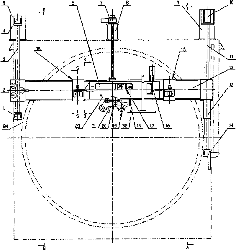
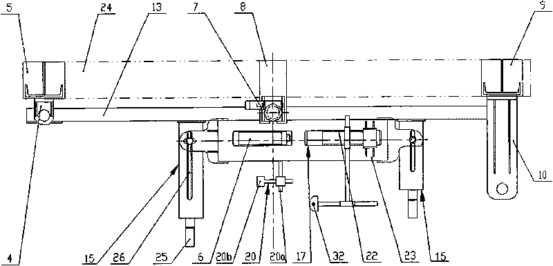
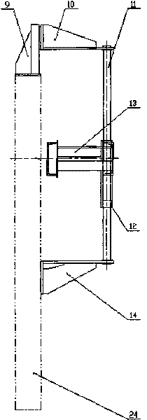
[0024] Such as figure 1 , figure 2 As shown, the present invention provides an automatic welding mechanical device of a numerically controlled reinforcement cage forming machine. The automatic welding mechanical device includes: a turntable frame 24; Two guide posts 11; the mobile support 13 that is arranged on one side of the turntable frame 24, the left and right sides of the mobile support 13 are slidably fitted on the first guide post 3 and the second guide post 11, and the top of the mobile support 13 is equipped with The elevator 7 that drives the mobile support 13 to move up and down; a box shell 23 is arranged on one side of the mobile support 13 .

[0025] The box shell 23 is provided with a hook 21 , a rolling mechanism 19 , a welding torch support mechanism 20 and a pitch adjusting mechanism 15 for adjusting the position and angle of the bo...


PUM


Abstract

The invention discloses an automatic wielding mechanical device for a forming machine of a numerical control reinforcing cage. The structure thereof comprises a turnplate rack, a first guide post, a second guide post, a movable bracket, a hoist, a case shell, a hook, a rolling mechanism, a welding-gun supporting mechanism and a screw pitch regulating mechanism; the left side and right side of the movable bracket are mounted on the first guide post and the second guide post in a sliding way; the top of the movable bracket is provided with the hoist driving the movable bracket to move up and down; the case shell is arranged at one side of the movable bracket and provided with the hook, the rolling mechanism, the welding-gun supporting mechanism and the screw pitch regulating mechanism; and the screw pitch regulating mechanism is used for regulating the position and angle of the case shell. The invention has the beneficial effects that: the automatic wielding mechanical device can automatically and coordinately complete welding operation of the reinforcing cage under the control of a control system, the regulation of different positions and angles of the case shell can be realized; with the rotation of the reinforcing cage, the hook can automatically hook the longitudinal steel bars, the welding-gun supporting mechanism and the reinforcing cage rotate synchronously and are always aligned with the intersection point of the hooping and the main reinforcement of the reinforcing cage, so as to perform automatic wielding in replacement of man power; the labor intensity is lowered, man power is saved, production efficiency is improved, and welding quality is bettered.

Description

technical field [0001] The invention relates to a numerical control reinforcement cage forming machine, in particular to an automatic welding mechanical device of the numerical control reinforcement cage formation machine. Background technique [0002] With the rapid development of expressways, viaducts and passenger dedicated lines in my country, a large number of steel cages are needed in pile foundation construction; at the same time, with the continuous increase in the height of buildings in cities and the strict control of noise in cities in recent years, bored piles are increasingly being used. Especially in developed coastal areas where there are many high-rise buildings and abundant groundwater, bored piles have many advantages such as large bearing capacity, low construction noise, little impact on adjacent buildings, and good construction safety. Therefore, bored piles with mud retaining walls have become The first choice for the foundation form of high-rise buildi...

Claims


Application Information

Patent Timeline
Patent Type & Authority Applications(China)
IPC IPC(8): B21F31/00B23K37/00
Inventor 陈振东
Owner TJK MACHINERY TIANJIN
Why Eureka
Try Eureka