Mechanical molding fiber reinforce plastic (FRP) electrolytic cell and preparation method thereof

An electrolytic cell and glass fiber reinforced plastic technology, applied in the electrolytic process, electrolytic components, plating tanks, etc., can solve the problems of uneven thickness of the coating layer, poor dipping of the aggregate, affecting the electrolytic output, etc., to achieve accurate size and improve smoothness. , the effect of saving manpower

Active Publication Date: 2010-05-05
GRIPM ADVANCED MATERIALS CO LTD +1
View PDF0 Cites 6 Cited by
  • Summary
  • Abstract
  • Description
  • Claims
  • Application Information

AI Technical Summary

Problems solved by technology

[0002] The traditional electrolytic cell adopts the form of reinforced concrete frame lined with glass fiber reinforced plastic. The glass fiber reinforced plastic of the inner lining layer is made by manual paste by workers in a small space, which is very easy to produce uneven thickness of glue coating, impregnated aggregate and bubbles. many, low density
It is easy to leak during use and requires regular maintenance, especially because the leaked acid-containing electrolyte will corrode the foundation of the equipment and the foundation of the plant, resulting in shutdown for maintenance and environmental pollution
Make it directly affect the electrolysis output, and need to spend a lot of money, causing great economic losses in the application

Method used


Image

  • Mechanical molding fiber reinforce plastic (FRP) electrolytic cell and preparation method thereof
  • Mechanical molding fiber reinforce plastic (FRP) electrolytic cell and preparation method thereof
  • Mechanical molding fiber reinforce plastic (FRP) electrolytic cell and preparation method thereof

Examples


Embodiment 1

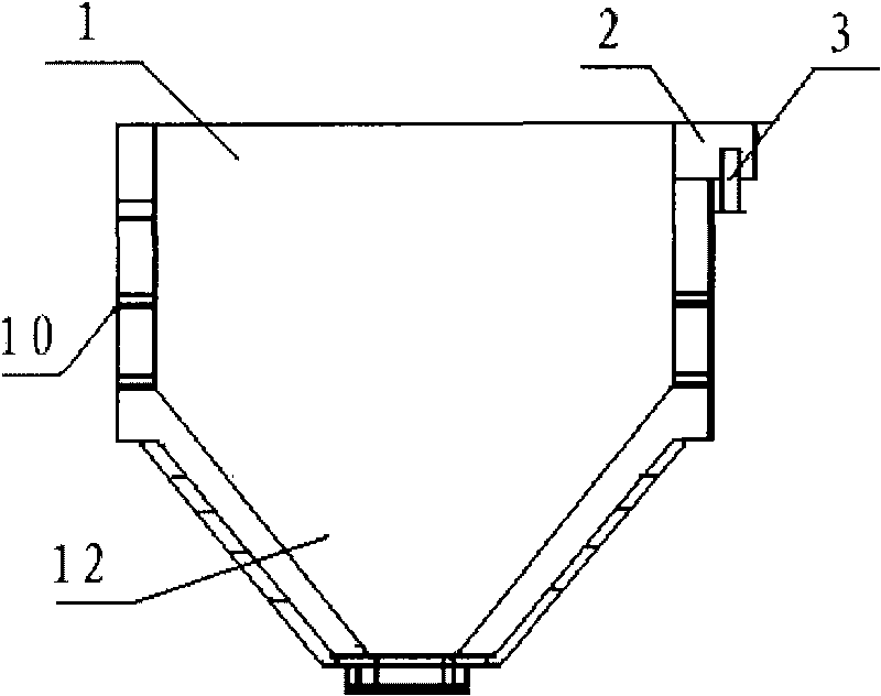
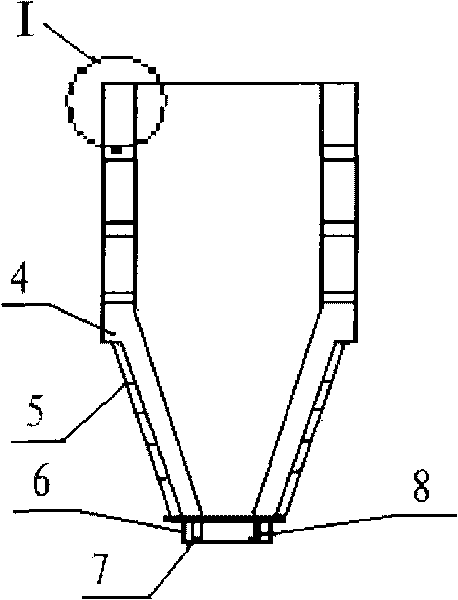
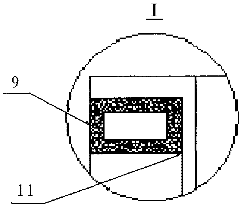
[0036] A mechanically formed FRP electrolytic cell, the FRP electrolytic cell is provided with an overflow tank 2 near the top of the tank, an overflow tank flange 3 is provided at the bottom of the overflow tank 2, and a discharge port 8 is provided at the bottom of the electrolytic cell , the electrolytic cell wall plate 10 is made of glass fiber reinforced resin, the electrolytic cell is composed of four cell wall plates 10, the four cell wall plates 10 are molded in pieces, and each cell wall plate 10 is divided into rectangular parts and Conical part, surrounded by four tank wall plates 10 to divide the electrolytic cell into two parts, the upper part is a rectangular tank 1, the lower part is a tapered tank 12, and the four inner corners and four outer corners of the joints of the tank wall boards 10 The corners are mechanically pressurized, and the inner corners are circular inner corners; grooves 11 are left when the rectangular part of the groove wall plate 10 is molde...


PUM

PropertyMeasurementUnit
densityaaaaaaaaaa

Abstract

The invention discloses a mechanical molding fiber reinforce plastic (FRP) electrolytic cell and a preparation method thereof, belonging to the technical field of the electrolytic cell and the preparation method thereof. The electrolytic cell is formed by four cell wall plates molded by separately mould pressing, the upper part is a rectangular groove, and the lower part is a cone-shaped groove; the rectangular parts of the cell wall plates are provided with grooves when in mould pressing, FRP rectangular tube reinforcing ribs are embedded inside the grooves and fixed with the cell wall plates into a whole, and the cone-shaped parts of the cell wall plates and strap-shaped reinforcing ribs form a whole by being simultaneously processed by mould pressing; the periphery of the connection parts between the rectangular parts and the cone-shaped parts of the cell wall plates is provided with a support groove bearing beam, and FRP is integrated with the electrolytic cell by pouring; and a mould pressing strengthening inner sleeve and a mould pressing strengthening outer sleeve are arranged between the bottom of the cone-shaped groove of the electrolytic cell and the periphery inside a discharge hole. The FRP electrolytic cell has good chemical corrosion resistance, physical property and insulating property. The manufacturing technique is energy-saving and labor-saving, and reduces the loss. Due to all the performances, the electrolytic cell has the service life more than ten years, is not needed to be overhauled by stopping production every year, reduces the maintenance cost, improves the electrolysis yield and saves the cost.

Description

technical field [0001] The invention belongs to the technical field of an electrolytic cell and a preparation method thereof, and in particular relates to a mechanically formed FRP electrolytic cell and a preparation method thereof. The electrolytic cell is mainly used in the electrolytic production of copper, zinc, nickel, etc. in the non-ferrous smelting industry. Background technique [0002] The traditional electrolytic cell adopts the form of reinforced concrete frame lined with glass fiber reinforced plastic. The glass fiber reinforced plastic of the inner lining layer is made by manual paste by workers in a small space, which is very easy to produce uneven thickness of glue coating, impregnated aggregate and bubbles. Many, low density. It is easy to leak during use and requires regular maintenance, especially because the leaked acid-containing electrolyte will corrode the foundation of the equipment and the foundation of the plant, resulting in shutdown for maintenan...

Claims


Application Information

Patent Timeline
Patent Type & Authority Applications(China)
IPC IPC(8): C25B9/00C25C7/00C25D17/02
Inventor 汪礼敏师守范王林山石龙张景怀班安平
Owner GRIPM ADVANCED MATERIALS CO LTD
Why Eureka
Try Eureka