
Intelligent meter and meter reading instrument

A meter and intelligent technology, applied in instruments, calorimeters, measuring devices, etc., can solve the problems of valve closing, strong magnetic field interference of magnets, and high manufacturing costs, and achieve convenient installation and meter reading, saving production costs, and copying. table speed effect

Inactive Publication Date: 2010-05-05
蓝景恒
View PDF0 Cites 15 Cited by
  • Summary
  • Abstract
  • Description
  • Claims
  • Application Information

AI Technical Summary

Problems solved by technology

The pulse-sending centralized copying system mainly has the following problems: heavy initialization and maintenance workload, strong magnetic field interference from magnets, and power consumption
In the practice of magnetic card (IC card) prepaid meter, it is found that there are mainly the following problems: IC card meter is also accumulated and measured by sending pulses. If there is artificial strong magnetic interference or strong electric shock, the chip will be damaged, so that it cannot be measured; If the recharge card password is stolen or deciphered, it will cause great losses to the water sales unit; the solenoid valve will be closed due to scale and impurities in the water when the solenoid valve is open for a long time, so that the user continues to use water without paying the fee, and charges The unit still doesn’t know anything about it, and once it is discovered, it will not be able to recover the excessive water bill from the user
"Passive" direct-reading water meter centralized reading system is currently used less in China, and we can only analyze and discuss the problems it may encounter from a technical point of view: whether it is photoelectric conversion technology, contact or resistance logic coding technology, or barcode Recognition technology has particularly high requirements for manufacturing and assembly processes, and the slightest deviation will cause errors and inaccurate carry in the remote transmission data of the watch, and its manufacturing cost is relatively high

Method used


Image

  • Intelligent meter and meter reading instrument
  • Intelligent meter and meter reading instrument
  • Intelligent meter and meter reading instrument

Examples


Embodiment Construction

[0035] The present invention will be further described below in conjunction with drawings and embodiments.

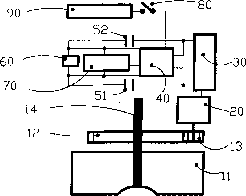
[0036] see figure 1 , the rotating shaft (14) supports the impeller (11) and the gear (12), and the impeller (11) drives the motor (20) to rotate, which can be transmitted through the variable speed gear set (12, 13), so that the motor can obtain a higher rotational speed. The number of teeth of the hour gear (12) should be greater than the number of teeth of the gear (13), and the transmission ratio is the ratio of the number of teeth of the gear (12) and the number of teeth of the gear (13). The gear (13) directly drives the motor (20) to rotate, and the motor (20) generates an electromotive force due to the rotation of the inner wire to cut the magnetic field line, and the magnitude of the electromotive force is proportional to the rotating speed of the motor (20). Therefore, it can not only provide information about the rotation of the impeller (11), but also provi...


PUM


Abstract

The invention relates to an electronic meter and a meter reading instrument, which is mainly used in wireless infrared water meter systems and meter reading systems and can also be used in gas meter systems, heater meter systems and other systems. The motor is driven to rotate by an impeller, thereby obtaining the rotating information of the impeller and transmitting electric energy to batteries. The signal is input into a singlechip via a rectification circuit; the functions of analog-to-digital conversion, calculation, data storage and signal transmission of the singlechip are utilized to acquire and process the information of the motor, and store, transmit and display the data; and in addition, one meter head can be shared by multiple users, and the output pipe of each user is provided with an impeller and a motor. The meter reading instrument comprises a transmitting and receiving circuit, a singlechip system, a storage unit, a display screen, an alarm, a peripheral circuit and a minitype printer; the meter reading instrument can read and process the information transmitted by the meter, and display the information on the display screen; and the minitype printer can print payment notes.

Description

technical field [0001] The invention relates to an electronic measuring meter and a meter reading instrument, in particular to a measuring instrument for wireless transmission. It is mainly used in wireless infrared water meter system and meter reading system, and can also be used in gas meter, heating meter and other systems. Background technique [0002] With the increase of urban population and high-rise buildings, the traditional manual meter reading can only adapt to the relatively small urban population. This traditional meter brings about the increase of management department costs, increased labor intensity of meter readers, and missed reading, Various disadvantages such as less copying and arrears of fees have become increasingly prominent, which has seriously hindered the development of the industry. At the same time, it shows that management efficiency is extremely low and social benefits are extremely poor. It is the only way to introduce modern high-tech and im...

Claims


Application Information

Patent Timeline
IPC IPC(8): G01F15/06G01K17/00G08C23/04G08C17/02H02J7/14
Inventor 蓝景恒
Owner 蓝景恒
Learn More