
Simplified hydraulic reciprocating diaphragm pump

A technology of reciprocating pumps with simplified structure, applied to pumps with flexible working elements, pumps, liquid variable displacement machines, etc., can solve the problems of easy wear of plunger packing, large leakage, complex structure of hydraulic end, etc., and achieve structural The effect of simple and external shape, reducing manufacturing and use costs, and optimizing equipment placement conditions

Inactive Publication Date: 2012-03-07
HANGZHOU DACHAO PETROCHEM EQUIP
View PDF3 Cites 0 Cited by
  • Summary
  • Abstract
  • Description
  • Claims
  • Application Information

AI Technical Summary

Problems solved by technology

If the sealing of the plunger is to be maintained, the cylinder block still needs to be disassembled, so there are still problems of difficult maintenance and high cost
[0004] The plunger type high pressure reciprocating pump is a commonly used equipment when high pressure and large flow fluid needs to be provided, but it has the disadvantages of large leakage and easy wear of the plunger packing
When the fluid is mixed with granular solids, the failure rate is higher and cannot meet the needs of the process
Although the existing high-pressure diaphragm plunger reciprocating pump can meet the needs of transporting impurity-containing fluids, the structure of its hydraulic end is quite complex, usually including flushing oil pumps, propelling oil pumps, electromagnetic reversing valves, pressure detection, and PLC. And other electrical equipment, resulting in bulky machine, expensive, difficult to popularize

Method used


Image

  • Simplified hydraulic reciprocating diaphragm pump
  • Simplified hydraulic reciprocating diaphragm pump
  • Simplified hydraulic reciprocating diaphragm pump

Examples


Embodiment Construction

[0040] Referring to the accompanying drawings, the present invention will be described in detail below.

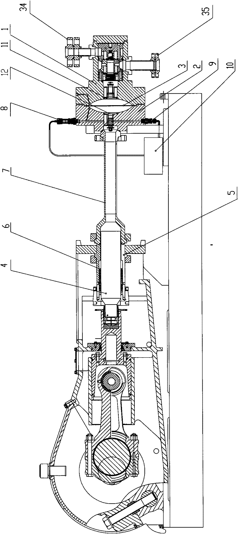
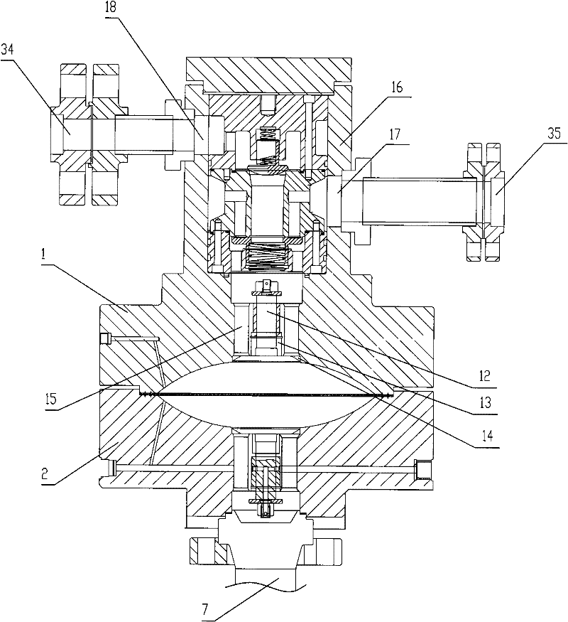
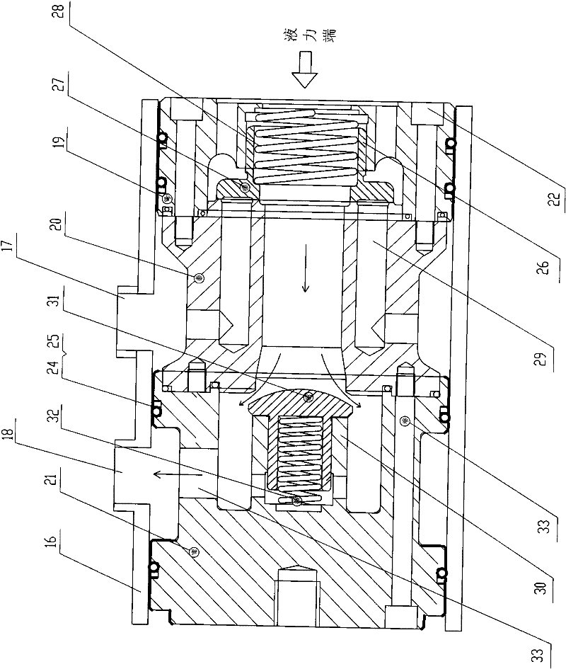
[0041]In this embodiment, the hydraulic diaphragm reciprocating pump includes a fluid end and a power end. The hydraulic end includes the cylinder block 2 connected to the pump head 1, the hydraulic oil cavity, the hydraulic oil internal circulation pipeline and the oil pool 10, and the diaphragm 3 is set between the pump head 1 and the cylinder block 2; the power end includes the motor, the cam , crankshaft, plunger 4 and stuffing box, the rear end of plunger 4 is connected with the crankshaft; 5 is sealed by a seal 6, which is a stuffing box ring arranged on the inner wall of the plunger sleeve 5. The front end of the plunger casing 5 is connected to the cylinder body 2 through the oil pipe 7, and the connection between the plunger casing 5 and the oil pipe 7, and between the oil pipe 7 and the cylinder body 2 is connected by a flange. Of course, the screw connection me...


PUM


Abstract

The invention relates to a reciprocating pump and aims to provide a simplified hydraulic reciprocating diaphragm pump. The pump comprises a hydraulic end and a power end; the hydraulic end comprises a cylinder body connected with a pump head, a diaphragm is arranged between the pump head and the cylinder body; the power end comprises a plunger, the back end of the plunger is connected with a crank shaft; the plunger is movably arranged in the plunger sleeve and slides back and forth inside the plunger sleeve, a sealing part is arranged between the plunger and the plunger sleeve so as to realize sealing, the front end of the plunger sleeve is connected with the cylinder body through an oil pipe and is communicated to the hydraulic oil side of the diaphragm; and a depressurization exhaust valve bank and a oil filling valve bank are separately connected through pipelines to form an independent oil pool and are separately communicated to the hydraulic oil side of the diaphragm through channels arranged in the cylinder body. The structure and external shape of the reciprocating diaphragm pump are simpler, the production difficulty and cost are reduced, an enormous amount of labor cost is saved, the working intensities of installation, maintenance and repair can be reduced, the efficiency is greatly increased, the cost is reduced, and the configuration method is flexible.

Description

technical field [0001] The present invention relates to a reciprocating pump. More particularly, the present invention relates to a hydraulic diaphragm reciprocating pump with a simplified structure. Background technique [0002] In the current hydraulic diaphragm reciprocating pump (or reciprocating diaphragm pump), the static system located behind the diaphragm and providing deformation tension for the diaphragm is generally called the fluid end, including the cylinder block, hydraulic oil chamber, and hydraulic oil internal circulation. Pipeline or oil pool and other parts; the dynamic system that will provide hydraulic pressure for the fluid end is called the power end, including motors, cams, crankshafts, plungers or plunger packings and other parts. However, the layout of the hydraulic end and the power end of a common hydraulic diaphragm reciprocating pump is mixed. For example, in the Chinese invention patent "Inner circulation pressure balance ultra-high pressure h...

Claims


Application Information

Patent Timeline
Patent Type & Authority Patents(China)
IPC IPC(8): F04B43/067
Inventor 杨树东
Owner HANGZHOU DACHAO PETROCHEM EQUIP
Learn More