
Visible light LED wireless communication light receiving antenna

A technology of light-emitting diodes and light-receiving antennas, used in optical fiber radio, optical fiber transmission, electromagnetic wave transmission systems, etc., can solve the problems of limiting the size of light-receiving antennas, unable to meet small size requirements, and high receiver noise, and achieve good light reception. effect, good short focus convergence effect, the effect of widening the reception angle and range

Inactive Publication Date: 2010-05-12
NANJING UNIV OF POSTS & TELECOMM
View PDF0 Cites 10 Cited by
  • Summary
  • Abstract
  • Description
  • Claims
  • Application Information

AI Technical Summary

Problems solved by technology

However, the price of the detector will increase with the increase of its photosensitive area, and the larger the photosensitive area, the smaller the receiver bandwidth, and the greater the receiver noise; the tapered optical fiber is placed behind the convex lens, the structure is complex, and the cost is high. And it will limit the size of the light-receiving antenna; the sensor positioning and aiming tracking system is expensive, difficult to implement, and the sensitivity is not high, and it cannot meet the small size requirements

Method used


Image

  • Visible light LED wireless communication light receiving antenna
  • Visible light LED wireless communication light receiving antenna
  • Visible light LED wireless communication light receiving antenna

Examples


Embodiment Construction

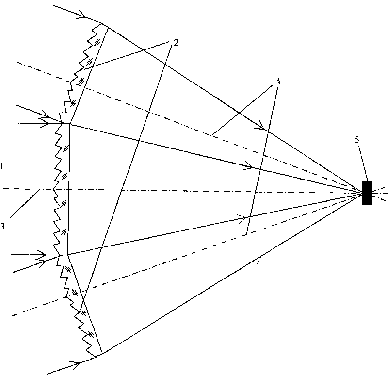
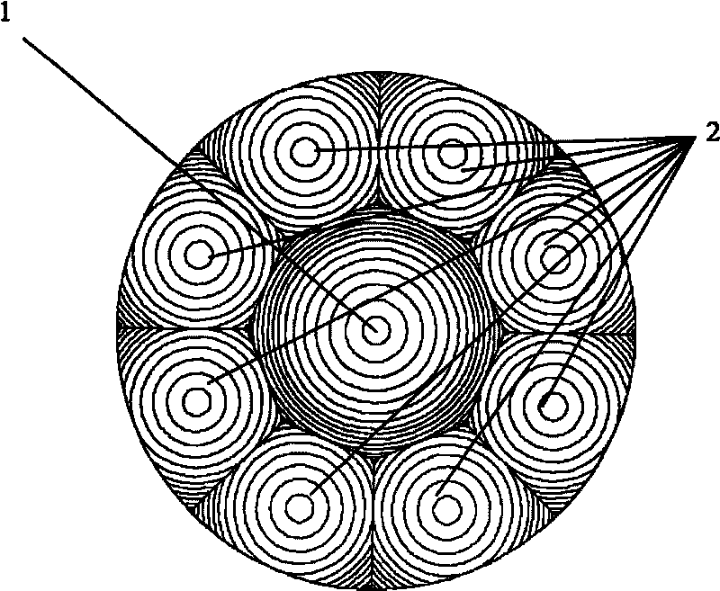
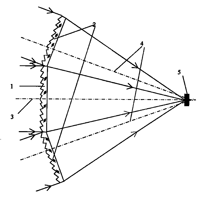
[0018] An optical receiving antenna for wireless optical communication proposed by the present invention consists of a main Fresnel lens and several secondary Fresnel lenses bonded to form a "table-shaped" structure. The top surface of the "terrace" is a regular polygonal main Fresnel lens made of PMMA material or other optical materials, and its side is surrounded by multiple secondary Fresnel lenses of the same shape that are symmetrical to the center of the main Fresnel lens. combined.

[0019] see figure 1 Shown example, this receiving antenna main body is made of Fresnel lens, comprises a main Fresnel lens 1, several Fresnel lenses 2 and photodetector 5, and described main Fresnel lens 1 is regular polygon; So Each sub-Fresnel lens 2 is bonded with the main Fresnel lens 1 at a fixed angle, and at the same time, it is symmetrical with the axis of the main Fresnel lens 1 and bonded to each other; the main Fresnel lens 1 and each sub-Fresnel lens The Neil lens 2 forms a "m...


PUM


Abstract

The invention relates to a visible light LED wireless communication light receiving antenna. The antenna is of a trapezoid structure formed by bonding a plurality of Fresnel lenses comprising a principal Fresnel lens (1) and plural subordinate Fresnel lenses (2); the principal Fresnel lens is the top face of the trapezoid and the subordinate Fresnel lenses are the lateral faces of the trapezoid; the principal Fresnel lens and the subordinate Fresnel lenses receive incoming optical signals from different directions with the range constrained in the angle formed by a principal optical axis (3) and a subordinate optical axis (4), and focus the light energy on the surface of a receiver (5) so as to expand receiving angle and receivable light energy. The Fresnel lenses are thin and have good short focus focusing effect, and the shapes of the antenna can be combined at will according to actual receiving condition. The invention is simple in structure, small in size, light in weight and low in cost, has large light receiving angle and good receiving performance, and is easy to implement.

Description

technical field [0001] The invention relates to a light-receiving antenna in a wireless optical communication system, which can ensure high-efficiency light reception while reducing the geometric size of the light-receiving antenna, and can especially improve the light-receiving effect when signal light is obliquely incident. It belongs to the technical field of optical communication equipment manufacturing. Background technique [0002] Visible light LED (light emitting diode) has many excellent characteristics such as high brightness, high reliability, low energy loss and long life, and can be used for display, lighting, traffic signal indication, etc. While the visible light LED is used as a light source for indoor lighting, it has many advantages as a signal light source for wireless communication. It uses optical signals as the carrier and transmits optical signals through the atmosphere as the transmission medium. It has the characteristics of large information capaci...

Claims


Application Information

Patent Timeline
Patent Type & Authority Applications(China)
IPC IPC(8): H04B10/00H04B10/2575
Inventor 徐宁徐丹彤钱晨
Owner NANJING UNIV OF POSTS & TELECOMM
Learn More