Radio frequency superconducting cavity with slit waveguide structure for superconducting accelerator

A technology of radio frequency superconducting cavity and slit waveguide, which is applied in the field of radio frequency superconducting cavity, can solve the problems of weak absorption of high-order modes, and achieve the effects of reducing processing difficulty, reducing production cost, and saving time and cost.

Inactive Publication Date: 2012-01-04
PEKING UNIV
View PDF0 Cites 0 Cited by
  • Summary
  • Abstract
  • Description
  • Claims
  • Application Information

AI Technical Summary

Problems solved by technology

For ordinary high-average-current-intensity superconducting cavities, the attenuation of high-order modes is outside the beam tube at both ends of the superconducting cavity, so its absorption of high-order modes is relatively weak, and can only reach the BBU threshold of the order of 100mA

Method used


Image

  • Radio frequency superconducting cavity with slit waveguide structure for superconducting accelerator
  • Radio frequency superconducting cavity with slit waveguide structure for superconducting accelerator
  • Radio frequency superconducting cavity with slit waveguide structure for superconducting accelerator

Examples


Embodiment Construction

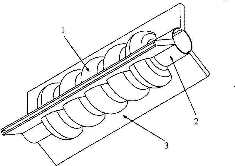
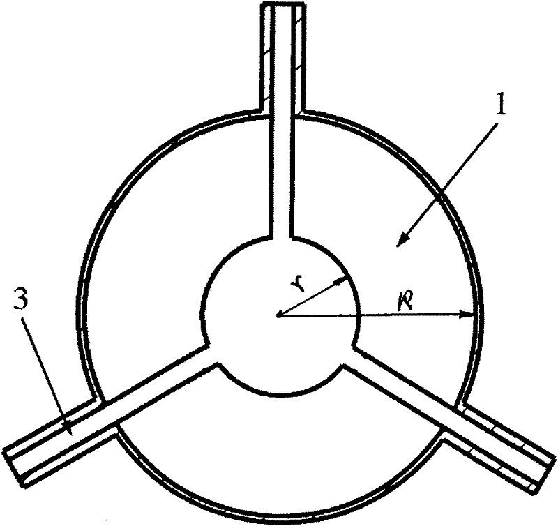
[0014] The radio frequency superconducting cavity of the band slit waveguide structure that the present invention proposes is used for superconducting accelerator, and its structure is as follows figure 1 As shown, it includes a plurality of elliptical spherical cavities 1 , beam tubes 2 and wing-shaped slot waveguides 3 . A plurality of elliptical spherical cavities 1 are connected in series, and the two ends of the multiple elliptical spherical cavities connected in series are bundle tubes 2, and the outer walls of each elliptical spherical cavity 1 and the bundle tubes 2 at both ends are evenly distributed along the circumference. The slits of each elliptical spherical cavity and the slits of the bundle tubes at both ends are connected through corresponding wing-shaped slit waveguides.

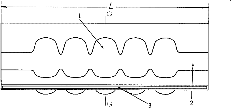
[0015] In the above-mentioned radio frequency superconducting cavity, the contour line of the elliptical spherical cavity can be concave, such as Figure 4 As shown, it can also be a low-l...


PUM


Abstract

The invention relates to a radio frequency superconducting cavity with a slot waveguide structure for a superconducting accelerator, which belongs to the technical field of accelerator physics. The radio frequency superconducting cavity comprises multiple oval spherical cavities, bundle tubes and alary slit waveguides, wherein the multiple oval spherical cavities are connected with one another inseries; both ends of the multiple oval spherical cavities which are connected with one another are the bundle tubes; each oval spherical cavity and the outer walls of the bundle tubes at the two endsare uniformly distributed with multiple slits along the circumferential direction; and the slits of each oval spherical cavity and the slits of the bundle tubes at the two ends are connected by the corresponding alary slit waveguides. The radio frequency superconducting cavity of the invention has super-high attenuation of a dipole module and a quadrupole module, so that ERL of GeV magnitude reaches the average current intensity of ampere magnitude; the radio frequency superconducting cavity can reach a BBU threshold value over the ampere magnitude; the radio frequency superconducting cavity can be formed by punching at one time due to no weld joint in a high electric field; therefore, machining difficulty is greatly reduced, time and cost for product production are reduced, the products are suitable for mass production, and the production cost is reduced.

Description

technical field [0001] The invention relates to a radio frequency superconducting cavity with a slit waveguide structure used for a superconducting accelerator, and belongs to the technical field of accelerator physics. Background technique [0002] At present, β=1 superconducting cavities for accelerating electrons in the world generally use ellipsoidal cavities, such as Tesla (TESLA) superconducting cavities, low loss (Low loss) superconducting cavities and reentrant superconducting cavities. These superconducting cavities can increase the allowable acceleration current intensity by appropriately increasing the beam aperture of the cavity. However, due to the limitation of the structure, the maximum flow intensity of the current ordinary superconducting cavity can only reach the order of 100mA in the energy recovery accelerator (hereinafter referred to as ERL) of the final energy of GeV level, such as the KEK-ERL model of Japan KEK -2 superconducting cavity [T.Furuya et a...

Claims


Application Information

Patent Timeline
Patent Type & Authority Patents(China)
IPC IPC(8): H05H7/00H05H7/16H05H7/20
Inventor 刘振超
Owner PEKING UNIV
Why Eureka
Try Eureka