
Concentrating solar tile capable of supplying heat and generating power

A technology of concentrating solar energy and solar watts, which is applied in the directions of solar thermal energy, solar thermal collectors using working fluid, solar thermal power generation, etc. Efficiency, the effect of improving utilization

Inactive Publication Date: 2010-05-19
安徽国源节能技术研究院有限公司
View PDF0 Cites 14 Cited by
  • Summary
  • Abstract
  • Description
  • Claims
  • Application Information

AI Technical Summary

Problems solved by technology

[0002] At present, the existing solar heating and power generation systems are separated. The solar water heater technology is very mature, but the installation and utilization efficiency of the solar water heater is not high, especially the installation of the solar water heater is placed on the top of the building, which is inconvenient to install. And it cannot be well matched with the building, which affects the overall image of the building; solar photovoltaic power generation technology has also been gradually applied, but due to the low efficiency of solar power generation, high cost, complicated installation of solar panels, and a large area, it is especially difficult to In urban applications, due to the impact of high-rise buildings blocking sunlight, solar energy cannot be fully used, which greatly hinders the application and promotion of solar energy. At present, there are also concentrated solar photovoltaic applications, some of which are solar photovoltaic tracking systems, which are complicated to manufacture, poor in concentrating effect, and expensive. Expensive, high cost of use and maintenance, difficult to promote; some are tracking-free concentrating solar applications, the manufacturing process is complicated, and it is very inconvenient to install on the roof. The service life of the entire component, there are many problems in the solar thermal and photovoltaic applications of the above solar energy that need to be solved urgently

Method used


Image

  • Concentrating solar tile capable of supplying heat and generating power
  • Concentrating solar tile capable of supplying heat and generating power
  • Concentrating solar tile capable of supplying heat and generating power

Examples


Embodiment Construction

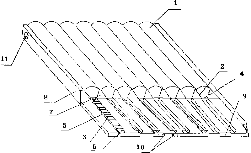
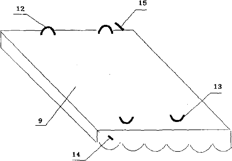
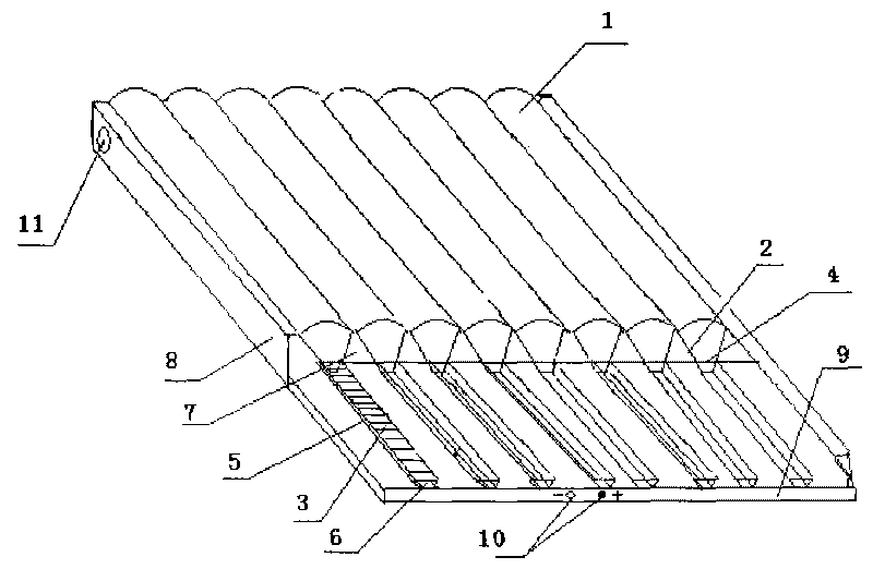
[0014] see figure 1 , figure 2 , the present invention includes: 1. Cylindrical waveform concentrator, 2. Aluminum-coated reflector, 3. Solar cell, 4. Glass plate on top of the cell, 5. Solar cell backplane, 6. Solar cell panel cooling pipe , 7. Vacuum heat collecting tube, 8. Aluminum alloy outer frame, 9. Heat insulation substrate, 10. Battery board output terminal, 11. Hot water collection tube, 12. Protrusion, 13. Groove, 14. Cooling water inlet pipe , 15, hot water outlet pipe. During implementation, after the cylindrical waveform concentrator 1 is casted, engraved, and polished, the light-gathering direction of the small lens is determined, and the solar cell backplane 5 is bonded to the solar cell panel cooling pipe 6 for standby, and the solar cell sheet 3 is one Paste the solar cells on the back plate 5 of the solar cells, and weld the solar cells 3 in series and parallel, connect the wires directly to the output terminals 10 of the solar cells, and then cover the ...


PUM


Abstract

The invention discloses a concentrating solar tile capable of supplying heat and generating power, which adopts light concentration and heat collection integrated technology. Firstly, a cylindrical waveform condenser is covered on the uppermost layer of the solar tile so that the focus of the sunlight just falls on a solar cell panel at the underside; two sides of the underside of the condenser are provided with an aluminized film reflector respectively; when rays are irradiated on the reflectors, the rays are reflected and converged to the solar cell panel; a radiating tube is arranged under the cell panel, and the middle of the cell panel is provided with cooling water for reducing the temperature of the cell panel; and the warm water flowing out from the radiating tube is baffled and then enters a vacuum heat collecting tube of the body so that the warm water is further heated in the heat collecting tube, and the hot water is delivered to a hot water collecting barrel of the last solar tile, thus, the hot water is gradually pushed upwards, and the hot water in the solar tile of the uppermost layer is directly delivered to the house for later use so as to finish the whole water circulating process. The lower end of the solar tile is provided with a solar cell output terminal, and the power emitted by the solar cell is conveyed into a storage cell or merged into a power grid after passing through an inverter so as to form the whole current loop.

Description

technical field [0001] The invention relates to a concentrating solar tile, in particular to a concentrating solar tile capable of heating and generating electricity. Background technique [0002] At present, the existing solar heating and power generation systems are separated. The solar water heater technology is very mature, but the installation and utilization efficiency of the solar water heater is not high, especially the installation of the solar water heater is placed on the top of the building, which is inconvenient to install. And it cannot be well matched with the building, which affects the overall image of the building; solar photovoltaic power generation technology has also been gradually applied, but due to the low efficiency of solar power generation, high cost, complicated installation of solar panels, and a large area, it is especially difficult to In urban applications, due to the impact of high-rise buildings blocking sunlight, solar energy cannot be full...

Claims


Application Information

Patent Timeline
IPC IPC(8): E04D13/18F24J2/10F24J2/05F24J2/24F24J2/46H02N6/00H02J7/00H02J3/38F24S10/40F24S10/70F24S23/70H02S20/25H02S40/22H02S40/44
CPCY02E10/44Y02E10/563Y02B10/14Y02B10/22Y02B10/12Y02B10/10Y02B10/20Y02B10/70Y02E10/56Y02E10/60
Inventor 王子韩
Owner 安徽国源节能技术研究院有限公司
Learn More