Charge pump circuit working at extra low voltage

A charge pump, working technology, applied in the direction of electrical components, adjusting electric variables, output power conversion devices, etc., to achieve a good matching effect

Inactive Publication Date: 2010-05-19
ZHEJIANG UNIV
View PDF0 Cites 9 Cited by
  • Summary
  • Abstract
  • Description
  • Claims
  • Application Information

AI Technical Summary

Problems solved by technology

[0009] In order to solve the problem that the traditional charge pump circuit works under extremely low voltage, the present invention adopts the body-driven current mirror structure, and the gate of the current mirror is controlled by the control signal, thereby realizing the parallel relationship between the MOS tube function and the current mirror function

Method used


Image

  • Charge pump circuit working at extra low voltage
  • Charge pump circuit working at extra low voltage
  • Charge pump circuit working at extra low voltage

Examples


Embodiment Construction

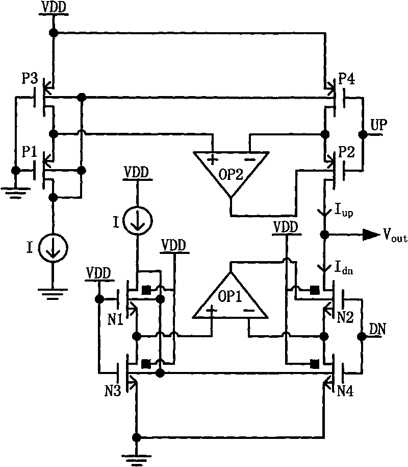
[0030] Such as figure 2 As shown, the charge pump circuit for extremely low voltage operation of the present invention includes a first N-type MOS transistor N1, a second N-type MOS transistor N2, a third N-type MOS transistor N3, a fourth N-type MOS transistor N4, a first P-type MOS transistor P1, the second P-type MOS transistor P2, the third P-type MOS transistor P3 and the fourth P-type MOS transistor P4 constitute the body drive current mirror of the common source common body, the first operational amplifier OP1 and the second operational amplifier Amplifier OP2.

[0031] The positive input terminal of the first operational amplifier OP1 is connected to the source of the first N-type MOS transistor N1 and the drain of the third N-type MOS transistor N3, and the negative input terminal of the first operational amplifier OP1 is connected to the second N-type MOS transistor N3. The source of the MOS transistor N2 is connected to the drain of the fourth N-type MOS transisto...


PUM


Abstract

The invention discloses a charge pump circuit working at extra low voltage, comprising a common-source common-body body drive current mirror, a first operational amplifier and a second operational amplifier, wherein the common-source common-body body drive current mirror consists of a first N-type MOS tube, a second N-type MOS tube, a third N-type MOS tube, a fourth N-type MOS tube, a first P-type MOS tube, a second P-type MOS tube, a third P-type MOS tube and a fourth P-type MOS tube, the second N-type MOS tube and the fourth N-type MOS tube not only realize the function of pulling down current tubes, but also realizes the function of pulling down the MOS tubes; the second P-type MOS tube and the fourth P-type MOS tube not only realize the function of pulling up the current tubes, but also realizes the function of pulling up the MOS tubes, thereby realizing the parallel connection relation of an MOS switch function and a current mirror function. The goal of increasing gains is achieved through the two operational amplifiers, i.e. the output resistance of the common-source common-body current mirror can be increased under low supply voltage.

Description

technical field [0001] The invention relates to the field of charge pump circuits, in particular to a charge pump circuit operating at extremely low voltage. Background technique [0002] Phase-locked loop (Phase-Locked Loop, PLL) has unique frequency multiplication and phase-locking functions, and has been widely used in wireless communication, clock recovery and other systems. With the further development of CMOS technology scaling down, integrated circuits (Integrated Circuits, IC) will enter the nanometer size, which increases the density of functional modules, the speed of devices and the ability of circuits to process signals. However, in order to satisfy reliability and avoid problems such as breakdown, hot carrier effect, and excessive power consumption density, its operating voltage is also proportionally reduced. Traditional analog circuits are usually designed for higher supply voltages, and many devices need to be cascaded. The supply voltage is gradually reduc...

Claims


Application Information

Patent Timeline
Patent Type & Authority Applications(China)
IPC IPC(8): H02M3/155
Inventor 周海峰韩雁梁筱杨伟伟
Owner ZHEJIANG UNIV
Why Eureka
Try Eureka