

Control system for detecting safety areas by combining infra-red technology and ultrasonic technology
A technology for control systems and safety areas, applied in general control systems, control/regulation systems, radio wave measurement systems, etc., can solve problems such as echo diffraction interference, inability to provide comprehensive protection, and non-jump change, etc., to eliminate errors Trigger action, improve dynamic anti-interference ability, high reliability effect
- Summary
- Abstract
- Description
- Claims
- Application Information
AI Technical Summary
Problems solved by technology
Method used
Image

Examples
Embodiment 1
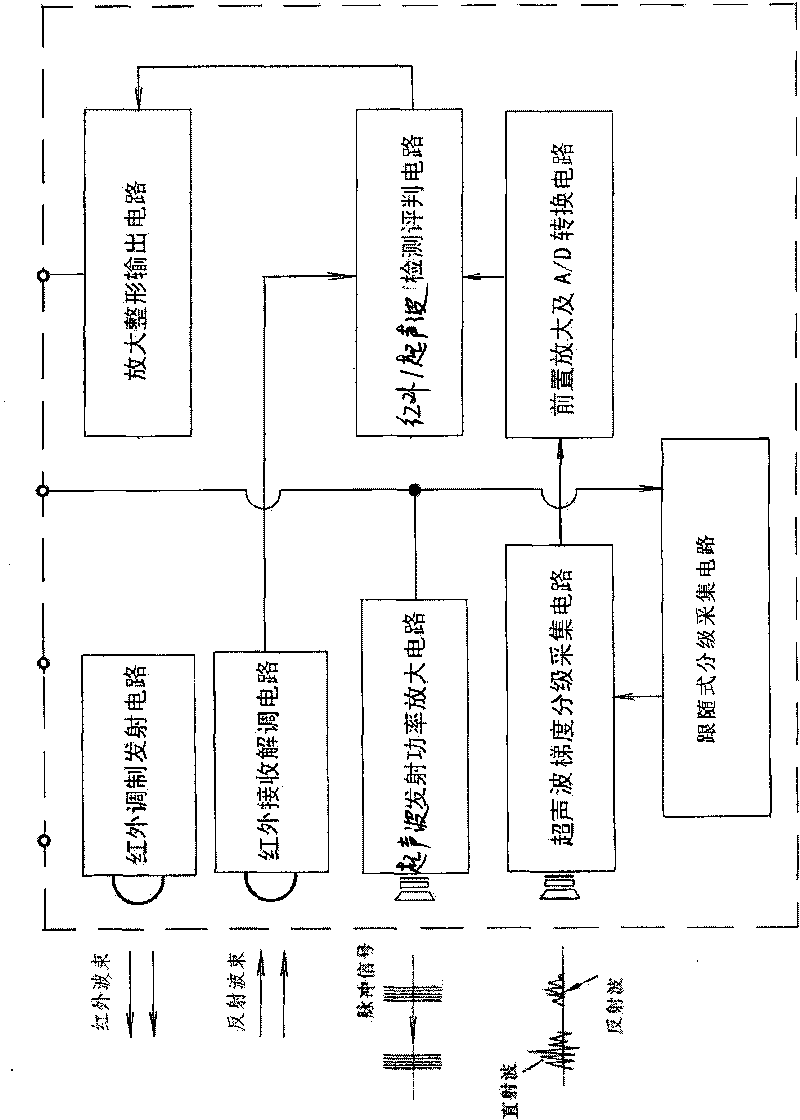
[0022] Embodiment 1: A control system for combining infrared light and ultrasonic waves to detect a safe area is composed of a PC microcomputer, a main controller and sensors.
[0023] PC microcomputer: The PC microcomputer adopts the window dialogue interface control method to realize the parameter and state setting of the main controller.
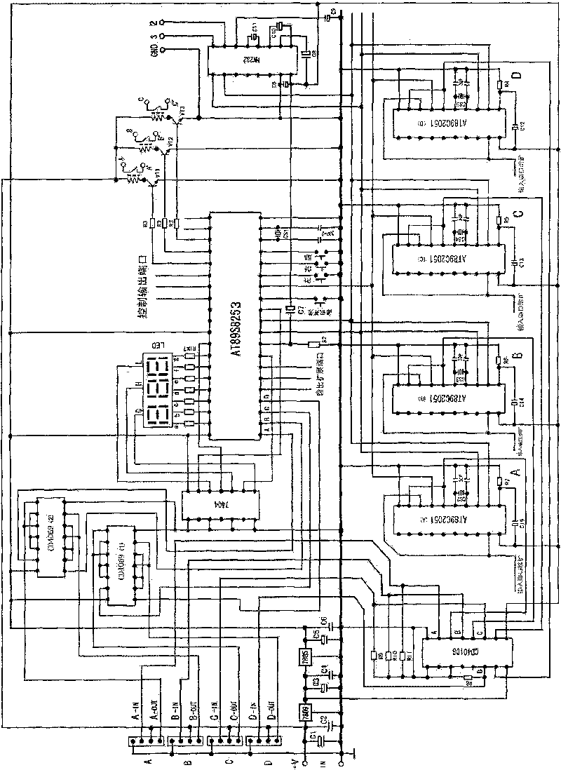
[0024] Main controller: The output control of the main controller adopts single-column operation, ultrasonic distance detection with bus-type collection priority and classification recognition, and four single-chip microcomputers AT89C2051 are independently single-column detection and calculation, and are collected in the main control CPU single-chip microcomputer AT89S8253 for signal by serial communication. Priority identification and evaluation, sensor number and detection distance value display and communication bus control of external PC micro-components.
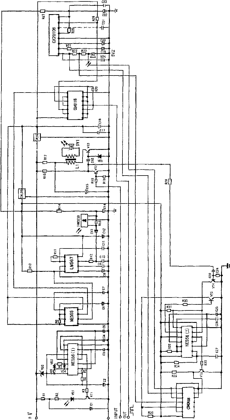
[0025] External power supply (+V) parallel filter capacitors C1 and C2 are gr...
PUM
 Abstract
Description
Claims
Application Information