

Multi-band bandstop filter and multi-band bandpass filter
A band-stop filter and band-pass filter technology, applied in waveguide devices, electrical components, circuits, etc., can solve the problems of limited double stop bands and difficulty in expanding 3 frequency bands, so as to reduce requirements, reduce sensitivity, The effect of reducing difficulty
- Summary
- Abstract
- Description
- Claims
- Application Information
AI Technical Summary
Problems solved by technology
Method used
Image

Examples
Embodiment
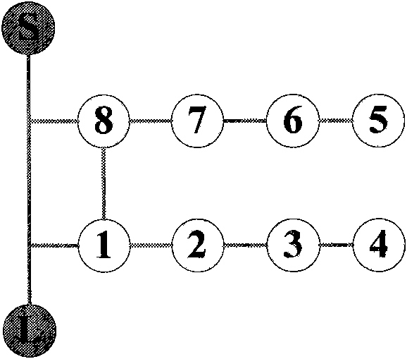
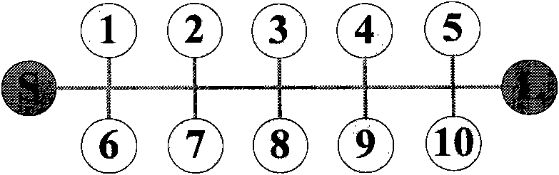
[0047] The design idea of the present invention has been given in detail above. It is mainly based on two dual stopband structures: the first as figure 2 As shown, two groups of resonant cavities are arranged on both sides of the main channel, which is used to design the topology structure of double stop band; the second one is as Figure 8 As shown, the two sets of resonant cavities are on the same side of the main channel ( Figure 8 ), which is used to expand the double stopband into a topology structure of 3 stopbands and 4 stopbands. Next, the two topological structures will be realized through two waveguide structures, the rectangular waveguide and the substrate-integrated waveguide, so as to prove the realizability of the multi-stopband structure proposed by the present invention. Finally, a schematic diagram of the 4-stop-band model based on SIW is given.
[0048] Such as figure 2 For the topology shown, a rectangular waveguide based dual stopband is designed. ...
PUM
 Abstract
Description
Claims
Application Information