Distributed visual sensing network-based movable navigation system

A technology of visual sensing and navigation system, applied in the field of communication and control, can solve the problems of relatively fixed work, difficult robot navigation, large amount of calculation and storage space, etc., and achieve the effect of high reliability

Inactive Publication Date: 2010-06-16
蒋平
View PDF7 Cites 16 Cited by
  • Summary
  • Abstract
  • Description
  • Claims
  • Application Information

AI Technical Summary

Problems solved by technology

[0003] 1. As far as image processing and scene understanding are concerned, the projection of the 3D world onto the 2D image plane through the pinhole projection model (used only by vertebrates) makes motion analysis itself pathological, such as rotation and movement in an impossible way. The way of disaggregation is mixed, which makes it difficult to achieve effective and reliable robot navigation
[0004] 2. As far as motion control is concerned, the arrangement of the head camera introduces more uncertainty due to the change of perspective caused by the movement of the camera
This makes the link between planning and control

Method used


Image

  • Distributed visual sensing network-based movable navigation system
  • Distributed visual sensing network-based movable navigation system
  • Distributed visual sensing network-based movable navigation system

Examples


Example Embodiment

[0023] Example 1

[0024] A mobile navigation system based on a distributed visual sensor network, including a visual network system and moving objects; the visual network system is mainly composed of a plurality of visual sensors connected through a wireless or wired network to provide an intelligent environment; the The moving object has a control box that can communicate with the vision network system, which controls the movement.

[0025] The visual sensor includes a camera and a microprocessor; the camera is used for capturing video information; the microprocessor is used for real-time optical flow extraction of the video information, monitoring of changes in background images, monitoring of intruding objects, and determining Motion entity, output the target motion information with entity tag or semantics.

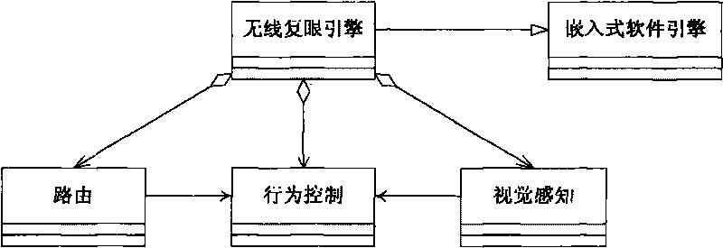
[0026] The camera is a CMOS camera or a closed-circuit surveillance camera; the camera is provided with an embedded software engine, and the embedded software engine...

Example Embodiment

[0028] Embodiment 2

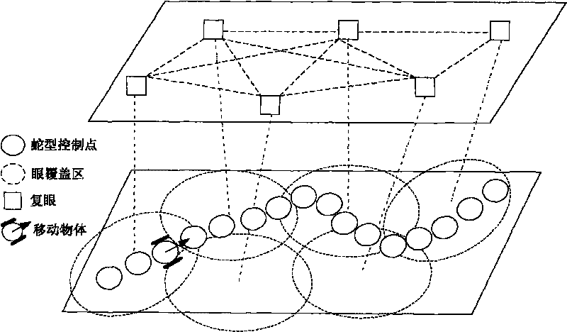
[0029] The overall system block diagram of this embodiment is as follows: figure 1 shown, including the following four parts:

[0030] 1. Install distributed vision sensors in the navigation environment. The vision sensor can be a dedicated CMOS camera or use the original closed-circuit surveillance camera, a microprocessor performs real-time optical flow extraction on video information, background image change detection, intrusion object detection, determination of moving entities, and output with Entity tagged / semantic target motion information. The vision sensor communicates with other vision sensors through a wireless or wired network to form a distributed vision network.

[0031] 2. A mobile vehicle wirelessly controlled by a distributed vision network. The mobile vehicle has very little on-board computing power, and only has simple emergency stop and obstacle avoidance capabilities, while the motion control is coordinated by the visual sensor th...


PUM


Abstract

The invention discloses a distributed visual sensing network-based movable navigation system, which comprises a visual network system and a movable object. The visual network system is mainly formed by connecting a plurality of visual sensors through wireless or wired networks, and is used for providing an intelligent environment; and the movable object is provided with a control box capable of being communicated with the visual network system, and is controlled to move by the visual network system. The system realizes navigation of non-intelligent vehicles in an extensive and strange environment by building the intelligent environment, not only has high reliability, but also is economical and practical.

Description

technical field [0001] The invention belongs to the technical field of communication and control, and relates to a mobile navigation system, in particular to a mobile navigation system based on a distributed visual sensor network. Background technique [0002] Existing mobile robots and smart car navigation usually rely on an on-board central computer and vision system to imitate the human brain to achieve centralized environment detection and information processing, so that the robot can acquire autonomous movement and behavior capabilities. However, due to the dynamic change and unstructured environment, such research faces a bottleneck problem of implementation complexity. For example, in order to accomplish autonomous navigation, considerable effort is required in cognition and knowledge representation, requiring considerable computational effort, with visual road signs to answer questions such as "Where am I?" and "What should I do now? "Have I been to this place?" Bas...

Claims


Application Information

Patent Timeline
IPC IPC(8): G05D1/00G01C11/00
Inventor 蒋平王晓年朱劲程宇成季刚
Owner 蒋平
Why Eureka
Try Eureka