Anode aluminium foil after treatment method for aluminium electrolytic capacitor

An aluminum electrolytic capacitor and anode aluminum foil technology, which is applied in capacitor electrodes, capacitor parts, chemical instruments and methods, etc., can solve the problem of shortening the boosting time of the formed foil, unstable riveting of the front and rear rolls, and can not effectively reduce the corrosion of aluminum powder on the surface of the foil. As well as the problems of particles and powder impurities in the holes, it can reduce the instability of riveting, shorten the boosting time and improve the quality of products.

Inactive Publication Date: 2010-06-16
GUANGXI HEZHOU GUIDONG ELECTRONICS TECH
View PDF0 Cites 14 Cited by
  • Summary
  • Abstract
  • Description
  • Claims
  • Application Information

AI Technical Summary

Problems solved by technology

[0003] The purpose of the present invention is to provide a post-treatment method for anode aluminum foil for aluminum electrolytic capacitors, which can solve the technical problem that the existing technology cannot effectively reduce the aluminum powder on the surface of the corroded foil and the impurity of particle powder in the hole, and can improve the static electricity of the anode aluminum foil. Capacity, and can effectively solve the problem of unstable riveting of the front and rear rolls during chemical formation and energy production while reducing the corrosion of powder on the surface of the foil, and at the same time shorten the boosting time of the formed foil

Method used


Image

  • Anode aluminium foil after treatment method for aluminium electrolytic capacitor
  • Anode aluminium foil after treatment method for aluminium electrolytic capacitor
  • Anode aluminium foil after treatment method for aluminium electrolytic capacitor

Examples


Embodiment 1

[0017] Preliminary preparation: first put the aluminum foil into the pretreatment solution and soak it for 120 seconds, wash it with pure water, and then put it into the corrosion A solution once and pass it at 470mA / cm 2 The electric current is treated for 120 seconds, cleaned with pure water and then put into the secondary corrosion B1 liquid to pass through 80mA / cm 2 The electric current is treated for 360 seconds, cleaned with pure water and then put into the secondary corrosion B2 liquid to pass through 80mA / cm 2 The electric current was treated for 360 seconds, and the pre-corrosion foil was obtained by cleaning with pure water. The following post-processing foils are the foils after the above treatments, referred to as pre-corrosion foils.

[0018] Post-treatment: Put the pre-corroded foil into the solution with a temperature of 30°C and a solution containing 5wt% nitric acid, use an ultrasonic frequency of 1KHz, a power of 0.5KW, and ultrasonic treatment for 60 second...

Embodiment 2

[0020] Preparatory conditions are the same as in Example 1.

[0021] Post-treatment: put the pre-corroded foil into a solution containing 4wt% nitric acid at a temperature of 40°C, use an ultrasonic frequency of 11KHz, a power of 1.5KW, and ultrasonic treatment for 45 seconds, take it out, clean it with pure water, and dry it.
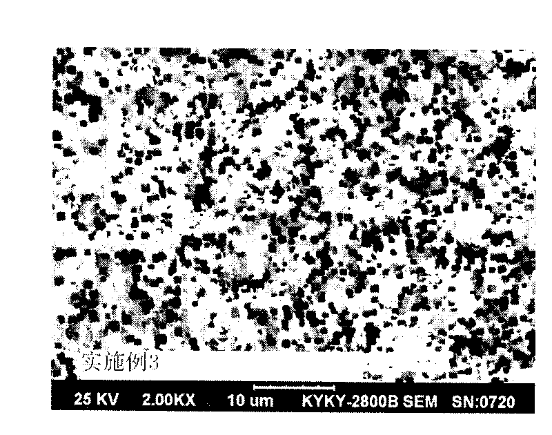
Embodiment 3

[0023] Preparatory conditions are the same as in Example 1.

[0024] Post-treatment: put the pre-corroded foil into a solution containing 4wt% nitric acid at a temperature of 50°C, and use an ultrasonic frequency of 20KHz and a power of 3.0KW for 45 seconds, take it out, clean it with pure water, and dry it.


PUM


Abstract

The invention relates to an anode aluminium foil after treatment method for an aluminium electrolytic capacitor, comprising the steps: pretreatment, first-grade corrosion A, second-grade corrosion B1, second-grade corrosion B2, after treatment and drying of corrosion foil, wherein the after treatment comprises the steps of chemical cleaning and ultrasonic cleaning; the after treatment comprises the steps of: putting aluminium foil processed by the second-grade corrosion B2 into 0.3-5wt% nitric acid solution at the temperature of 30-85 DEG C, and performing ultrasonic treatment for 5-60s at the ultrasonic frequency of 1-50KHz and the power of 0.5-5KW. Compared with the electrode corrosion foil prepared by the original technique, the electrostatic capacity of the cleaned anode aluminium corrosion foil is increased by 1-3%, and the pressure rising time is shortened by 6-12%.

Description

1. Technical field [0001] The invention relates to a method for corroding the anode aluminum foil of an aluminum electrolytic capacitor, in particular to a cleaning method during the corrosion process of the anode aluminum foil of the aluminum electrolytic capacitor. 2. Background technology [0002] The corrosion production process of aluminum electrolytic capacitor anode foil generally includes the following steps: pre-treatment of light foil, primary hole corrosion, secondary hole expansion corrosion, post-treatment (cleaning), drying, and foil corrosion. In order to expand the effective specific surface area of ​​the anode aluminum foil of aluminum electrolytic capacitors and increase the electrostatic capacity (specific capacity) per unit area, major production enterprises have made great improvements to the process, such as improving the process formula of pretreatment, the process formula of electrochemical corrosion and The number of poles, the time ratio of hole for...

Claims


Application Information

Patent Timeline
Patent Type & Authority Applications(China)
IPC IPC(8): H01G9/04B08B3/10B08B3/12
Inventor 宋洪洲蔡小宇熊传勇
Owner GUANGXI HEZHOU GUIDONG ELECTRONICS TECH
Why Eureka
Try Eureka