Transverse flux permanent-magnet planar motor

A technology of permanent magnet plane and transverse magnetic flux, applied in the direction of electrical components, electromechanical devices, electric components, etc., can solve the problems of low current control accuracy, limited mover stroke, complex motor structure, etc., and achieve improved current and electromagnetic force control High precision, high thrust density and power density, and the effect of eliminating mutual inductance between phases

Active Publication Date: 2010-06-16
HARBIN INST OF TECH
View PDF0 Cites 10 Cited by
  • Summary
  • Abstract
  • Description
  • Claims
  • Application Information

AI Technical Summary

Problems solved by technology

[0005] In order to solve the problems of limited mover stroke, low thrust density, complex structure of the motor and low current control precision in the permanent magnet synchronous planar motor, the present invention proposes a transverse flux permanent magnet planar motor

Method used


Image

  • Transverse flux permanent-magnet planar motor
  • Transverse flux permanent-magnet planar motor
  • Transverse flux permanent-magnet planar motor

Examples


specific Embodiment approach 1

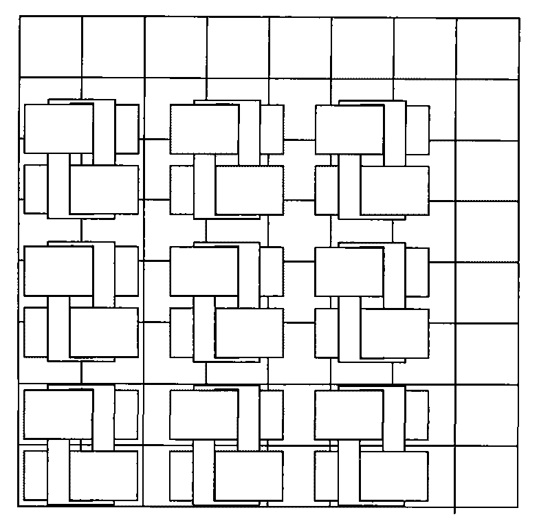
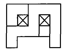
[0009] Specific implementation mode 1. Combination figure 1 and figure 2 Describe this embodiment, this embodiment is made up of primary and secondary; secondary is made up of permanent magnet array; primary is made up of several motor units, each motor unit is made up of m 2 Composed of phase armature units 1, m 2 A phase armature unit 1 forms a phase armature unit array 2 of m rows and m columns, and the row spacing of the phase armature unit array 2 is equal to the column spacing; each phase armature unit 1 is composed of a phase unit core 3 and the phase unit winding 4; each phase unit core 3 is composed of two core units 5 and has a tooth hole 71, and the tooth hole 71 is formed by overlapping the tooth slots 72 of the two core units 5, Each core unit 5 is made up of two teeth and a yoke segment; the two teeth are arranged along the horizontal direction of the cross section, and a yoke segment is connected between the two teeth; the two core units 5 are arranged along...

specific Embodiment approach 2

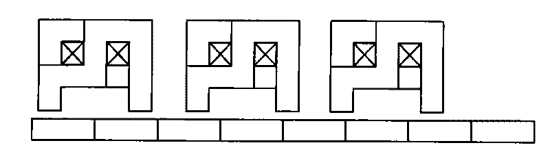
[0010] Specific embodiment two, combine Figure 3 to Figure 7 Describe this embodiment. The first difference between this embodiment and the specific embodiment is that each core unit 5 in the phase unit core 3 is composed of a long tooth 51, a short tooth 52, a high-level yoke segment 53, a low The horizontal yoke section 54 and a vertical yoke section 55 are composed; the long teeth 51 and the short teeth 52 are arranged along the horizontal direction of the cross section, and the long teeth 51 and the short teeth 52 are sequentially connected with high The horizontal yoke section 53, the vertical yoke section 55 and the low horizontal yoke section 54, the side root of the long tooth 51 is connected to the side of one end of the high horizontal yoke section 53, and the high horizontal yoke The other side of the section 53 is connected to the root of one side of the vertical yoke section 55, and the other side of the vertical yoke section 55 is connected to one end of the low...

specific Embodiment approach 3

[0011] Specific embodiment three, combine Figure 3 to Figure 5 This embodiment is described. The difference between this embodiment and the second embodiment is that the coil 41 is circularly wound on the upper part of the long tooth 51 or on the high horizontal yoke segment 53 or the vertical yoke segment 55 through the two tooth holes 7 described above. Phase-to-phase unit windings. Other compositions and connection methods are the same as those in the second embodiment.


PUM


Abstract

The invention discloses a transverse flux permanent-magnet planar motor, and relates to the filed of motors. The transverse flux permanent-magnet planar motor solves the problems of limited stroke of a rotor, low thrust density, complicated structure of the motor, low current control accuracy and the like in the conventional permanent-magnet planar motor. The primary of the motor consists of a plurality of motor units; each w motor units consist of m2 phase armature units; and the m2 phase armature units form a phase armature unit array; the intervals between rows and the intervals between columns are the same; each phase armature unit consists of a phase unit iron core and a phase unit winding; each phase unit iron core with perforations consists of two iron core units, the perforations are formed by overlapping tooth spaces of the two iron core units, two teeth of each iron core unit are arranged along the horizontal direction of a cross section, and a magnet yoke section is connected between the two teeth; a coil is wound into a phase of phase unit winding through the perforations; and the tooth pitch tau a between two adjacent phase unit iron cores along the X direction or Y direction is equal to [1+j/m]] tau p. In addition, the motor has the advantages of simple structure and easy realization of modulization, and the stroke of the motor is not limited.

Description

technical field [0001] The invention relates to the field of motors, in particular to a permanent magnet planar motor. Background technique [0002] Modern precision and ultra-precision processing equipment has an urgent need for high-response, high-speed, high-precision planar drive devices, such as machining, electronic product production, mechanical loading and unloading, manufacturing automated instrumentation equipment, and even robot drives. Usually these devices are powered by a rotary motor, and then converted into linear motion by mechanical devices such as belts and ball screws. Due to the complexity of the mechanical device, the transmission accuracy and speed are limited, and frequent adjustments are required, resulting in high cost, poor reliability, and large volume. The original planar driving device was realized by two directly driven linear motors, and a stacked driving structure was adopted. This structure increased the complexity of the transmission syste...

Claims


Application Information

Patent Timeline
Patent Type & Authority Applications(China)
IPC IPC(8): H02K41/02
Inventor 寇宝泉张千帆程树康
Owner HARBIN INST OF TECH
Why Eureka
Try Eureka