Pneumatic auxiliary threading device of numerical control electrospark wire-electrode cutting machine tool

A cutting machine and pneumatically assisted technology, used in attachments, electric processing equipment, metal processing equipment, etc., can solve the problems of molybdenum wire easily broken, easily detached from the guide wheel, easy to cut fingers by operators, and reduce labor intensity. , The effect of fast threading and low failure rate

Inactive Publication Date: 2010-06-23
浙江博雷重型机床制造有限公司
View PDF0 Cites 7 Cited by
  • Summary
  • Abstract
  • Description
  • Claims
  • Application Information

AI Technical Summary

Problems solved by technology

Its disadvantages: first, the molybdenum wire is easy to break when feeding the wire, and it is easy to break away from the V-shaped groove of the guide w

Method used


Image

  • Pneumatic auxiliary threading device of numerical control electrospark wire-electrode cutting machine tool
  • Pneumatic auxiliary threading device of numerical control electrospark wire-electrode cutting machine tool
  • Pneumatic auxiliary threading device of numerical control electrospark wire-electrode cutting machine tool

Examples


Embodiment 1

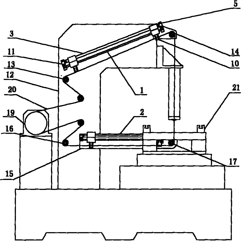
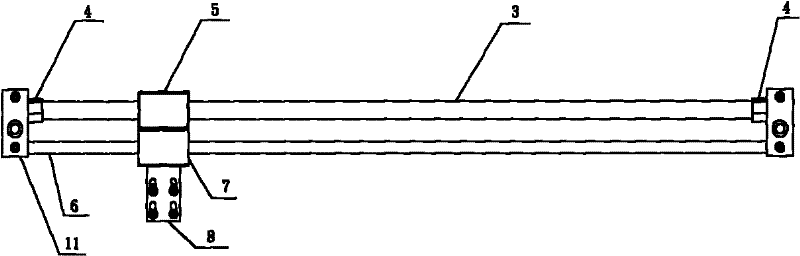
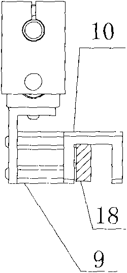
[0011] Embodiment 1: with reference to attached Figure 1~3 . A pneumatic auxiliary wire feeding device for a CNC wire cutting machine, which includes an upper wire feeder 1 and a lower wire feeder 2, the upper wire feeder 1 and the lower wire feeder 2 are provided with a magnetic rodless cylinder 3 and Two ends are provided with air inlet 4, magnetic rodless cylinder 3 is provided with magnetic rodless cylinder slide block 5, is provided with guide rail 6 below magnetic rodless cylinder 3, is provided with slide block 7 on guide rail 6 and is connected with magnetic rodless cylinder The slide block 5 is fixedly connected, and the lower end of the slide block 7 fixes the miniature cylinder 9 through the miniature cylinder holder 8, and the miniature cylinder 9 is connected with the pneumatic chuck seat 10.

[0012] The upper wire feeder 1 is fixed above the column 12 by the upper wire feeder fixing base 11 and is parallel to the upper row of wire wheels 13 and the upper guide...

Embodiment 2

[0015] Embodiment 2: A wire feeding method for a pneumatically assisted wire feeding device of a CNC wire cutting machine tool, in which the molybdenum wire 20 wound on the wire storage barrel 19 is wound around the upper wire wheel 13 and the molybdenum is clamped by the pneumatic chuck seat 10 The wire 20, the magnetic rodless cylinder slider 5 and the pneumatic chuck seat 10 slide along the guide rail 6 from the upper wire wheel 13 end to the upper guide wheel 14 end. After reaching the position, the pneumatic chuck seat 10 releases the molybdenum wire 20, and the molybdenum wire 20 Go around on the upper guide wheel 14, pass through the workbench 21 and go around on the lower guide wheel 17, then send it to the lower row of wire wheels 16 by the lower wire feeder 2 and then wind it in the wire storage barrel 19.


PUM


Abstract

The invention relates to a pneumatic auxiliary threading device of a numerical control electrospark wire-electrode cutting machine tool which is suitable for oil-contaminated and moist working environment with low fault rate, convenient threading and safe operation. The pneumatic auxiliary threading device of a numerical control electrospark wire-electrode cutting machine tool comprises an upper wire feeder and a lower wire feeder. The upper wire feeder and the lower wire feeder are provided with magnetic rodless cylinders, and air inlets are arranged at both ends; each magnetic rodless cylinder is provided with a magnetic rodless cylinder slider; a guide rail is arranged below the magnetic rodless cylinder and is provided with a slider which is fixedly connected with the magnetic rodless cylinder slider; and a mini-type cylinder is fixed at the lower end of the slider through a mini-type cylinder fixed base and is connected with a pneumatic collet chuck. The invention has the advantages that: firstly, the wire feeder is provided with the magnetic rodless cylinder so that the pneumatic auxiliary threading device of the numerical control electrospark wire-electrode cutting machine tool is suitable for oil-contaminated and moist working environment with low fault rate, convenient threading and safe operation, and secondly, molybdenum wires are clamped by the pneumatic collet chuck, thereby reducing the labor intensity of workers, improving the working efficiency and ensuring safer operation.

Description

technical field [0001] The invention relates to a pneumatic auxiliary wire feeding device for a CNC wire cutting machine tool which is suitable for oily and humid working environments and has low failure rate, convenient wire feeding and safe operation, and belongs to the technical field of CNC wire cutting machine tools. Background technique [0002] At present, in the structural design of CNC wire-cut electric discharge machine tools sold on the market, the upper molybdenum wires are all manually loaded without any auxiliary devices. Its disadvantages: First, the molybdenum wire is easy to break when feeding the wire, and it is easy to break away from the V-shaped groove of the guide wheel and the conductive block; second, the operator is easy to cut the fingers when feeding the wire; Large-stroke models cannot be threaded by one person. Contents of the invention [0003] Design purpose: To avoid the deficiencies in the background technology, to design a pneumatic auxil...

Claims


Application Information

Patent Timeline
IPC IPC(8): B23H11/00B23H7/02
Inventor 高尔荣谭广
Owner 浙江博雷重型机床制造有限公司
Why Eureka
Try Eureka