Metal plate material ring-shaped light spot laser impact forming method and device

A ring-shaped spot and laser shock technology, which is applied in laser welding equipment, metal processing equipment, welding equipment, etc., can solve the problems of low efficiency and easy cracking, and achieve the advantages of preventing lamination, improving smoothness, and short production preparation time Effect

Inactive Publication Date: 2010-06-23
JIANGSU UNIV
View PDF2 Cites 23 Cited by
  • Summary
  • Abstract
  • Description
  • Claims
  • Application Information

AI Technical Summary

Problems solved by technology

[0005] The purpose of the present invention is to solve the problems of easy cracking and low efficiency in the existing Gaussian distribution and uniform distribution laser beam shock forming methods, and utilize the hollow beam irradiation to ...

Method used


Image

  • Metal plate material ring-shaped light spot laser impact forming method and device
  • Metal plate material ring-shaped light spot laser impact forming method and device
  • Metal plate material ring-shaped light spot laser impact forming method and device

Examples


Embodiment 1

[0030] Such as figure 2 , 5 shown.

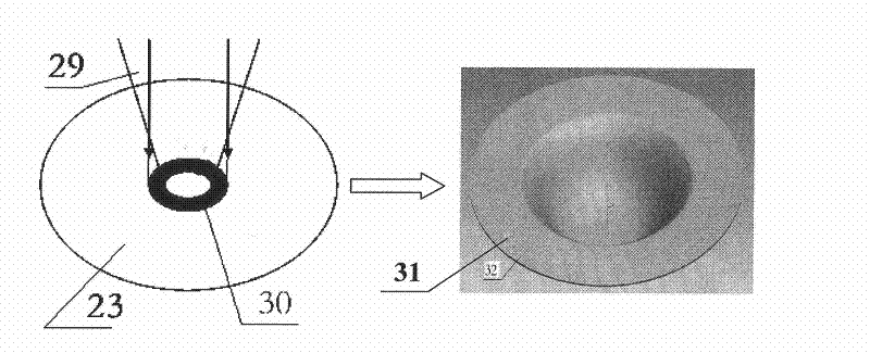
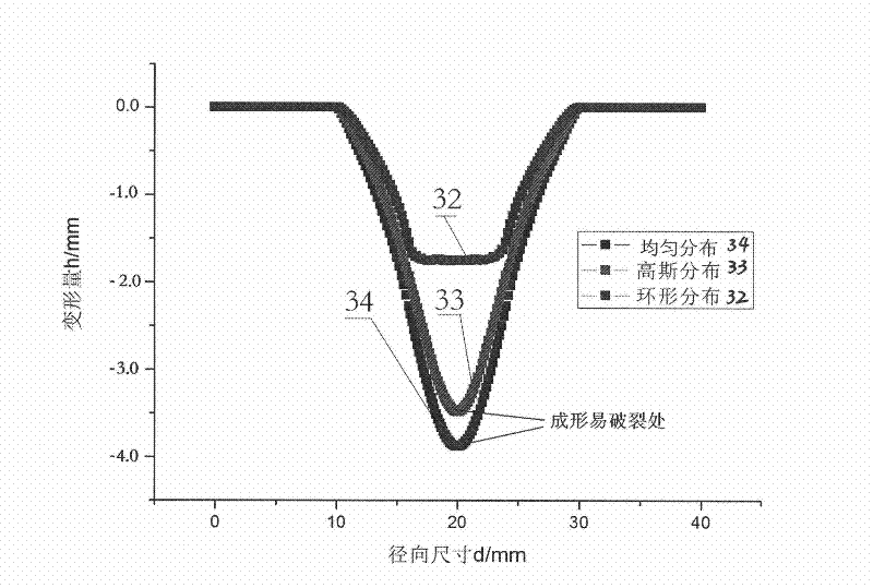
[0031] A laser shock forming method for ring-shaped spot of metal sheet, which adopts a high-power pulse laser, makes the adjustable laser beam emitted by the high-power pulse laser pass through the optical path system to form a ring-shaped laser spot, and makes the ring-shaped laser spot act on the surface of the workpiece system, The workpiece surface is subjected to laser-induced shock waves to produce rapid plastic deformation. Such as figure 2 As shown, according to the requirements of sheet shape / material / thickness and forming rules, as well as the signal of the forming detection feedback system, the central control system comprehensively adjusts the laser pulse width, laser energy, inner and outer diameter of the ring spot, and the impact position to obtain a reasonable The size and distribution of the impact force to obtain precise workpiece contours and improve forming efficiency.

[0032] During specific implementation, the ...

Embodiment 2

[0035] Such as Figure 1-5 shown.

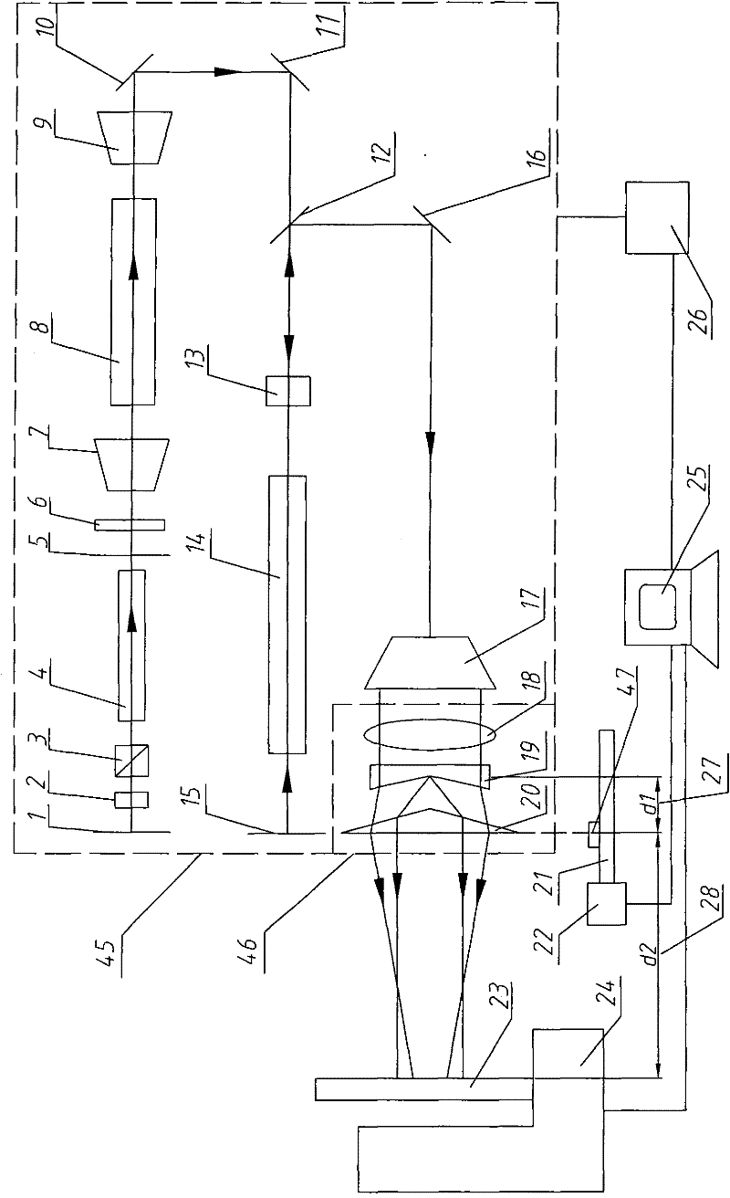
[0036] A ring-shaped spot laser impact forming device for sheet metal, which includes a laser generator power supply 26, a control device 25, a machine tool 24, a stepping motor 22, a guide rail 21, a laser generating system 45, and a ring-shaped spot forming adjustment device 46, and a control device 25 It is respectively electrically connected with the laser generator power supply 26, stepper motor 22 and machine tool 24. A movable workpiece system 23 is installed on the machine tool 24. On the top, the laser generator power supply 26 passes through a laser generating system 45 and then outputs an annular light spot to act on the workpiece. System 23, the stepper motor 22 is connected to the slider 47 on the guide rail 21 through a screw mandrel, and the ring-shaped spot forming adjustment device 46 is composed of a converging lens 18, a first conical lens 19 and a second conical lens 20, and the converging lens 18 is used as a ring-shaped...


PUM

PropertyMeasurementUnit
Pulse widthaaaaaaaaaa
The inside diameter ofaaaaaaaaaa
Outer diameteraaaaaaaaaa

Abstract

The invention provides a metal plate material ring-shaped light spot laser impact forming method and a device. The method is characterized in that a ring-shaped laser light spot is adopted to act on the surface of a work-piece system and then quick plastic deformation occurs on the surface of a work-piece under the function of impact wave induced by laser. The device is mainly composed of a lasergenerator power supply (26), a control device (25), a machine tool (24), a stepping motor (22), a guide rail (21) and a laser generating system (45). The laser generating system (45) interacts with acone lens set to generate a hollow light beam, and the hollow light beam is irradiated on the surface of the work-piece to form the ring-shaped light spot. The invention is beneficial for changing the distribution of the laser impact forming force, so as to prevent the cracking in the forming process, thereby improving the laser impact forming property and limit of a plate material, and increasing the finished product rate and the processing speed.

Description

technical field [0001] The invention relates to a method and device for plastic forming of sheet metal, in particular to a method and device for laser shock forming of sheet metal, in particular to a method and device for forming ring-shaped laser spot of sheet metal. Background technique [0002] As we all know, plastic forming of sheet metal, as one of the main methods of sheet metal forming, has occupied a very important position in the entire national economy. With the development of laser processing technology, laser shock sheet metal forming is widely used in many fields such as automobile, aviation and national defense industry due to the combination of material modification and strengthening and forming, and has the characteristics of ultra-high pressure, fast and high strain rate. potential application prospects. [0003] Domestic Jiangsu University Zhang Yongkang and others disclosed the invention patent "a laser shock precision forming method and device (ZL011340...

Claims


Application Information

Patent Timeline
IPC IPC(8): B23K26/00B23K26/08B23K26/06B23K26/18B23K26/064B23K26/356
Inventor 姜银方管海兵张永康王宏宇唐振州杨超君鲁金忠尤建钱晓明叶云霞方雷李志飞
Owner JIANGSU UNIV
Why Eureka
Try Eureka