Rectification speed increasing tower used for vertical axis wind turbine

A wind power generator, vertical axis technology, applied to wind power generators, wind power generators at right angles to the wind direction, motors, etc., can solve the problem of unsuitable applications for densely populated areas with the greatest power demand, low wind speed at start-up, wind energy utilization efficiency, and blade design And the difficulty of manufacturing and other issues, to achieve the effect of helping landscape design, improving the utilization rate of wind energy, and preventing birds from being harmed

Inactive Publication Date: 2010-06-23
HARBIN INST OF TECH
View PDF5 Cites 11 Cited by
  • Summary
  • Abstract
  • Description
  • Claims
  • Application Information

AI Technical Summary

Problems solved by technology

The horizontal axis wind turbine has low starting wind speed and high wind energy utilization efficiency. It is the mainstream equipment of the current wind turbine system and is widely used. However, the horizontal axis wind turbine also has the following disadvantages: (1) It is difficult to design and manufacture the blades; (2) The bending stress on the root of the blade is large; (3) It is necessary to install a windward adjustment device, and the surface of the wind rotor cannot always face the wind direction. Studies have shown that a deviation of the wind direction by 40° will reduce 50% of the energy utilization rate; (4) Mechanical The system is complex, the manufacturing cost is high, and it is difficult to achieve high reliability; (5) The nacelle of the horizontal axis wind turbine is placed on the top of a high tower, and the center of gravity of the unit is high, unstable, complex in structure and inconvenient for installation and maintenance; (6) The blade cutting airflow will generate a lot of aerodynamic noise. At the same time, it is difficult for many birds to survive under such high-speed blades, which will have a great impact on the ecological environment
[0003] Due to the above characteristics, horizontal axis generators are generally installed in areas with strong wind and sparse population in the wild, and are not suitable for use in densely populated areas with the greatest power demand, so they are also not suitable for small power generation needs such as homes and border posts.

Method used


Image

  • Rectification speed increasing tower used for vertical axis wind turbine
  • Rectification speed increasing tower used for vertical axis wind turbine
  • Rectification speed increasing tower used for vertical axis wind turbine

Examples


specific Embodiment 1

[0037] Specific implementation example 1: (fixed deflector type rectification speed-increasing tower)

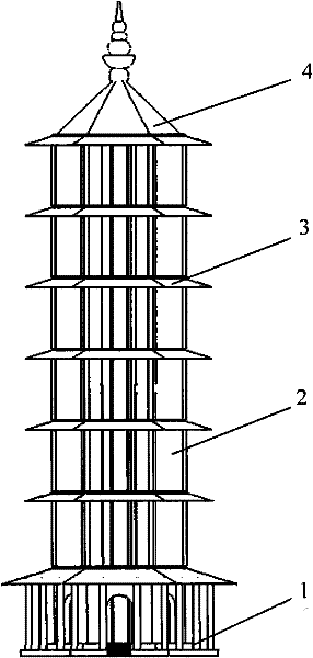
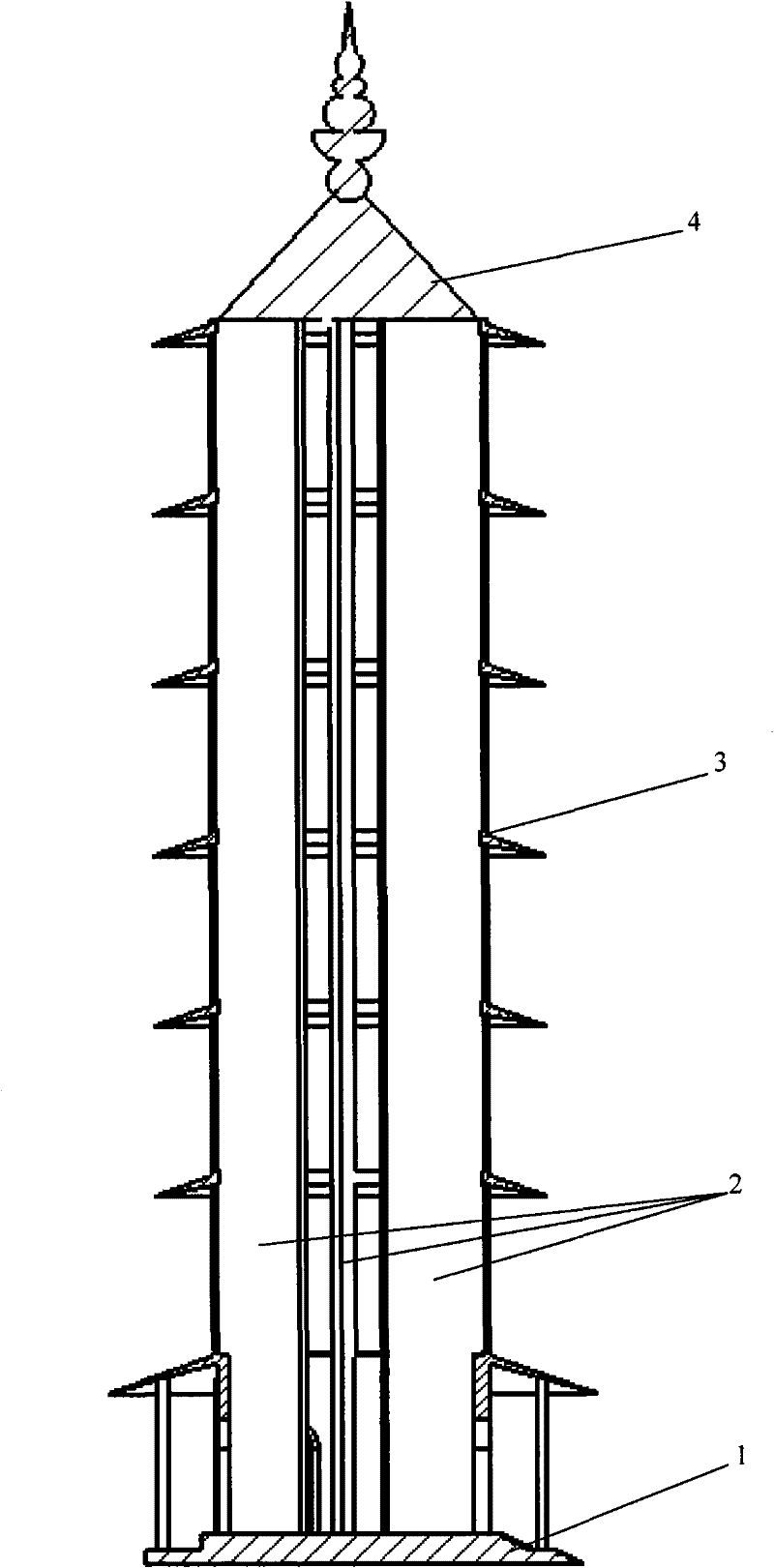
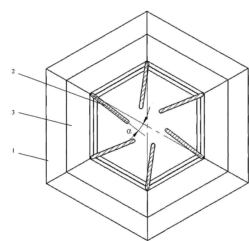
[0038] Fixed deflector type rectification growth tower such as figure 2 , image 3 As shown, the deflector is composed of a group (more than 4 pieces) of flat or curved plates, the upper end of which is connected to the tower eaves 3 or the tower top 4, and its lower end is connected to the tower base 1 or the tower eaves 3, and the deflector The groups are distributed in the circumferential direction with the tower center as the center and form a certain angle α with the radial direction (such as image 3 shown), the value range of α is 0-23°. The center of the tower presents a hollow columnar cavity, which is used to house vertical axis wind turbines.

specific Embodiment 2

[0039] Specific implementation example 2: (implementation scheme of deflector rotary adjustment method)

[0040]As shown in Figure 7(a), each deflector 2 is composed of a fixed part 21 and a movable part 22, wherein the upper end of the fixed part 21 is connected with the tower top 4, the lower end is connected with the tower base 1, and the movable part 22 passes through The rotating shaft 23 is connected with the fixed part 21, and the movable part 22 of the deflector can rotate around the rotating shaft 23 driven by external force. The adjustment method of the movable part of the deflector is shown in Figure 7(b). The motor 27 is connected to the reducer 25 through the coupling 26, the reducer is connected to the rotating shaft 23, and the rotating shaft 23 is controlled by the motor to rotate, thereby driving the movable part 22 to rotate. .

[0041] Assuming that the wind direction is from left to right, the left wind tunnel shown in Figure 7(a) is in the windward direct...

specific Embodiment 3

[0042] Specific implementation example 3: (implementation scheme of deflector push-pull adjustment mode)

[0043] As shown in Figure 8 (a), the deflector 2 is composed of a fixed part 21 and a movable part 22, wherein the lower part of the fixed part 21 is connected with the base 1, and the upper part is connected with the tower top 4, and the fixed part 21 and the movable part 22 The space is connected by a hinge 23, and the movable part 22 can rotate under the drive of external force. The adjustment method of the movable part of the deflector is shown in Figure 8 (b). The motor 27 is connected to the lead screw 28 through a coupling, and the lead screw is equipped with a sliding guide rail 29. The table 29 is slidable on the guide rod 25 . The motor 27 drives the lead screw 28 to rotate to drive the movable workbench 29 to move linearly along the guide rod 25, and the workbench 29 pushes the connecting rod 24 to move, thereby driving the movable part 22 of the deflector to ...


PUM


Abstract

The invention relates to a rectification speed increasing tower used for a vertical axis wind turbine. The appearance of the rectification speed increasing tower is a layer or multiple layers of tower-shaped structures. The rectification speed increasing tower comprises a tower base (1), a fairing (2), a tower brim (3) and a tower top (4). The center of the tower is provided with a hollow columnar chamber, and the inside of the chamber is used for installing a vertical axis wind turbine set. The invention has the advantages that the speed increasing ratio of a speed increaser is reduced, the stress condition and the working condition of the vertical axis wind turbine are improved, the stability of the wind turbine is increased, the service life thereof is prolonged, the design difficulty of the wind turbine is lowered, the manufacture and transportation costs of the wind turbine are reduced, the environment is protected, the appearance is beautiful and the like.

Description

technical field [0001] The invention relates to a rectifying speed-increasing device for a vertical-axis wind power generator, which belongs to the fields of new energy and mechanical engineering. technical background [0002] A wind turbine is an energy conversion device that converts wind energy into mechanical energy. According to the rotation direction of the wind rotor, the structure of the wind rotor and its position in the airflow, the wind turbine can be divided into horizontal axis wind turbine (HAWT) and vertical axis wind turbine. machine (VAWT). The horizontal axis wind turbine has low starting wind speed and high wind energy utilization efficiency. It is the mainstream equipment of the current wind turbine system and is widely used. However, the horizontal axis wind turbine also has the following disadvantages: (1) It is difficult to design and manufacture the blades; (2) The bending stress on the root of the blade is large; (3) It is necessary to install a win...

Claims


Application Information

Patent Timeline
Patent Type & Authority Applications(China)
IPC IPC(8): F03D3/04
CPCY02E10/74Y02P70/50
Inventor 姚英学姚奇周亮汤志鹏
Owner HARBIN INST OF TECH
Why Eureka
Try Eureka