
Cantor fractal microstrip array antenna for ku waveband

A technology of Cantor fractal and microstrip array, which is applied in the direction of antennas, antenna arrays, electrical components, etc., to achieve the effects of size reduction, simple manufacture, and good return loss performance

Inactive Publication Date: 2013-10-23
XIAMEN UNIV
View PDF0 Cites 0 Cited by
  • Summary
  • Abstract
  • Description
  • Claims
  • Application Information

AI Technical Summary

Problems solved by technology

At present, there is no report on the combination of Cantor's fractal microstrip structure, array structure, and photonic bandgap structure and its application in the ku band.

Method used


Image

  • Cantor fractal microstrip array antenna for ku waveband
  • Cantor fractal microstrip array antenna for ku waveband
  • Cantor fractal microstrip array antenna for ku waveband

Examples


Embodiment Construction

[0032] The present invention will be further described below in conjunction with embodiment and accompanying drawing.

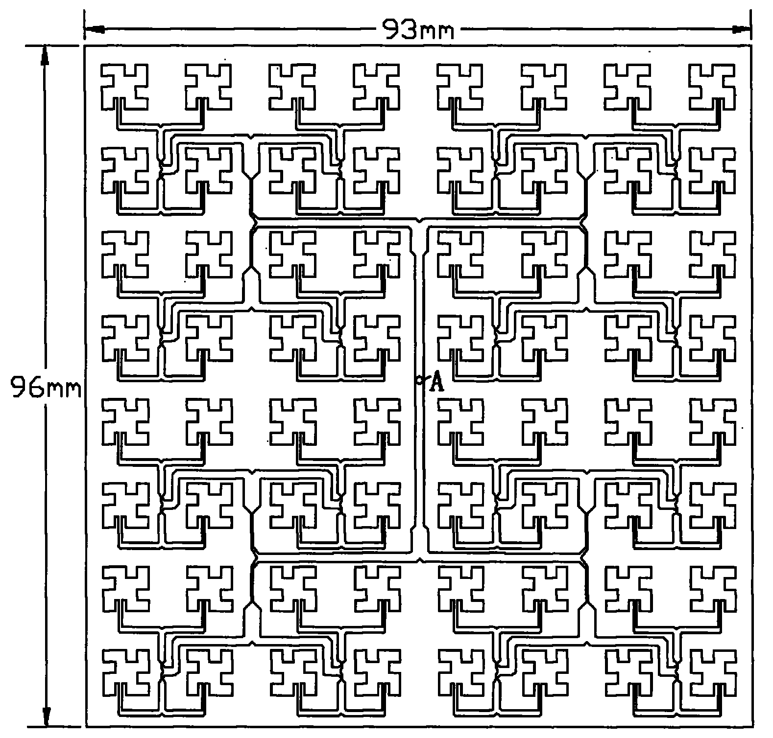
[0033] see figure 1 , the present invention uses a microstrip structure, the front as figure 1 It is an 8×8 array composed of first-order Cantor fractal antenna elements, and the back is an integral copper-clad structure ground plate.

[0034] The overall array is rectangular, with a side length of 93mm×96mm and a thickness of 1.5mm±0.05mm.

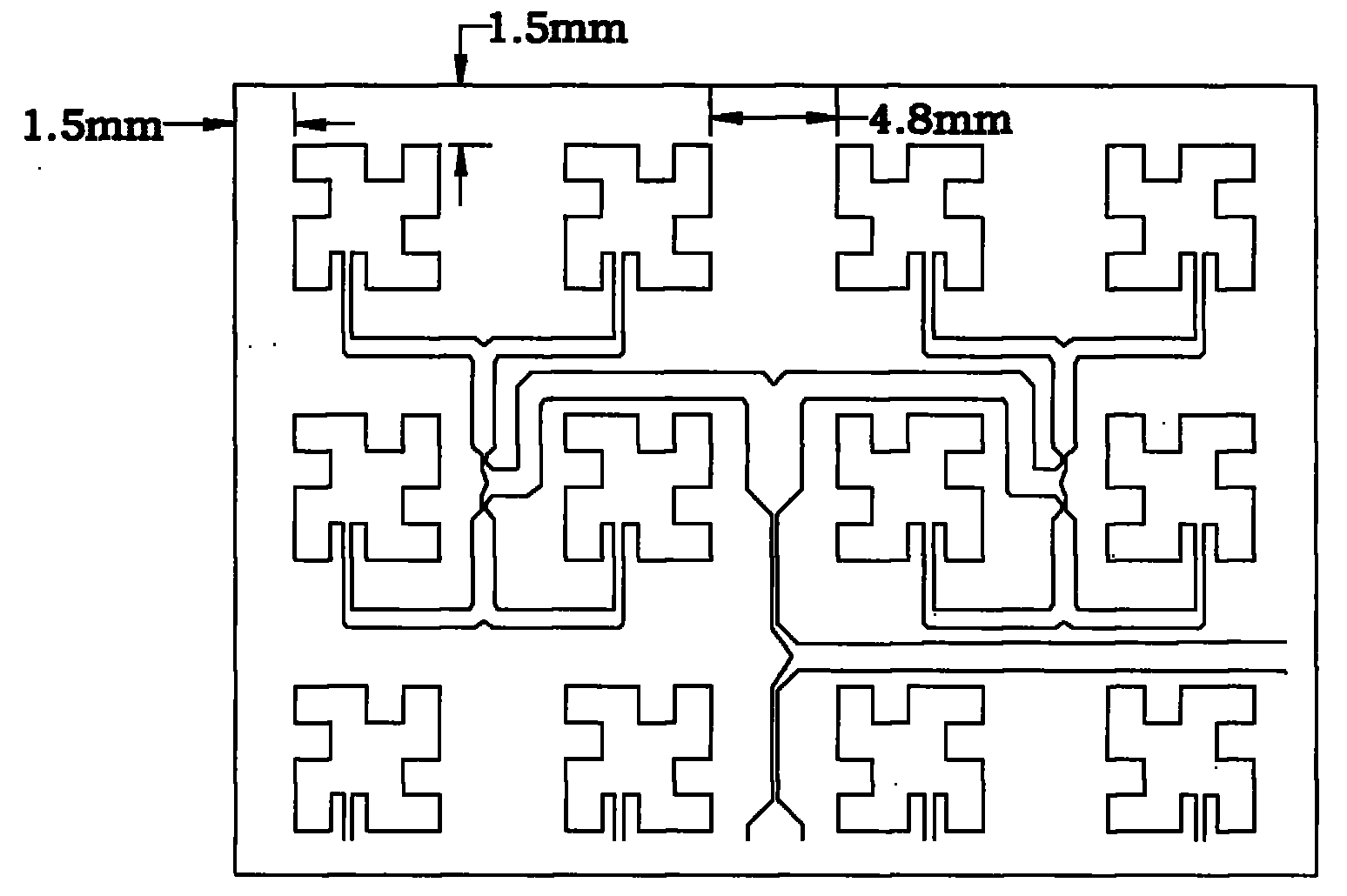
[0035] see figure 2 , the distance between each array element is 4.8mm±0.1mm, and the distance between the radiator and the boundary is 1.5mm±0.1mm.

[0036] Each array element is connected by a microstrip structure, and the width and length of the microstrip line are matched by a quarter-wavelength matching line.

[0037] When in use, an antenna feeding point A is provided at the center of the substrate, and the distance from the feeding point A to each array element is basically equal. The feeding method is coaxial ...


PUM


Abstract

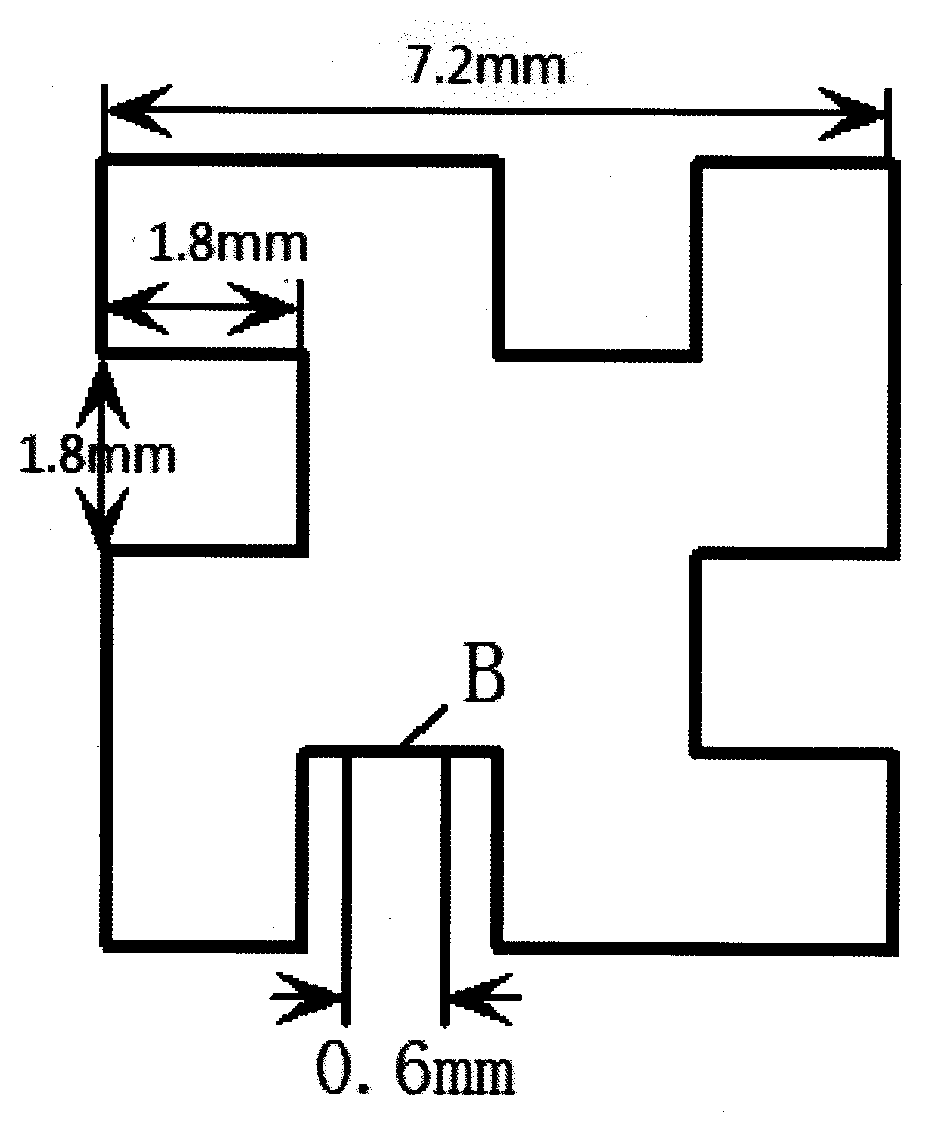
A Cantor fractal microstrip array antenna for ku waveband relates to a microstrip antenna. The invention provides a cantor fractal microstrip array antenna for ku waveband with the characteristics of small size, good return loss performance and strong directional radiation, which is provided with a medium substrate, wherein the medium substrate is provided with a Cantor fractal antenna radiation patch, and the structure of the Cantor fractal antenna radiation patch one-level Cantor fractal structure; an antenna feed point is arranged on the position B along the inner concave central line of the lower edge of the Cantor fractal antenna radiation patch, the antenna array is formed by 64 array elements including 8 rows and 8 lines, the rows are parallel with each other at equidistance, and the lines are parallel with each other at equidistance; all the array elements are connected by microstrip lines; and the photonic band gap structure of the back of the array, which is taken as the ground plate, is formed by 4 Cantor fractal combinations, and the distance between the array elements is zero.

Description

technical field [0001] The invention relates to a microstrip antenna, in particular to a Cantor fractal microstrip array antenna for Ku band. Background technique [0002] Ku-band is the frequency band of live broadcast satellites. Generally, the downlink receiving frequency band is between 11.7 and 12.2 GHz. It is not easily disturbed by microwave radiation. It uses multi-feed source forming beam technology to effectively cover the country. Its wide frequency band can transmit various services and information. [0003] The satellite receiving antenna is a device used to collect weak signals from satellites and remove noise as much as possible. The commonly used satellite receiving antenna is a metal parabola, which is responsible for reflecting the satellite signal to the feed source and tuner at the focal point. A high-quality satellite receiving antenna requires high manufacturing precision, corrosion-resistant surface, strong wind resistance, high efficiency, high gain...

Claims


Application Information

Patent Timeline
Patent Type & Authority Patents(China)
IPC IPC(8): H01Q13/08H01Q21/00
Inventor 周建华柳青蔡立绍游佰强严新金
Owner XIAMEN UNIV
Learn More