Motor control device, drive device, and hybrid drive device

A control device and motor technology, applied in the direction of motor generator control, AC motor control, control of electromechanical transmission, etc., can solve problems such as loss reduction

Active Publication Date: 2010-06-23
AISIN AW CO LTD
View PDF4 Cites 17 Cited by
  • Summary
  • Abstract
  • Description
  • Claims
  • Application Information

AI Technical Summary

Problems solved by technology

[0009] In the conventional method for determining the intermediate DC voltage described above, SVpwm and DPWM are sometimes used i

Method used


Image

  • Motor control device, drive device, and hybrid drive device
  • Motor control device, drive device, and hybrid drive device
  • Motor control device, drive device, and hybrid drive device

Examples


Embodiment 1

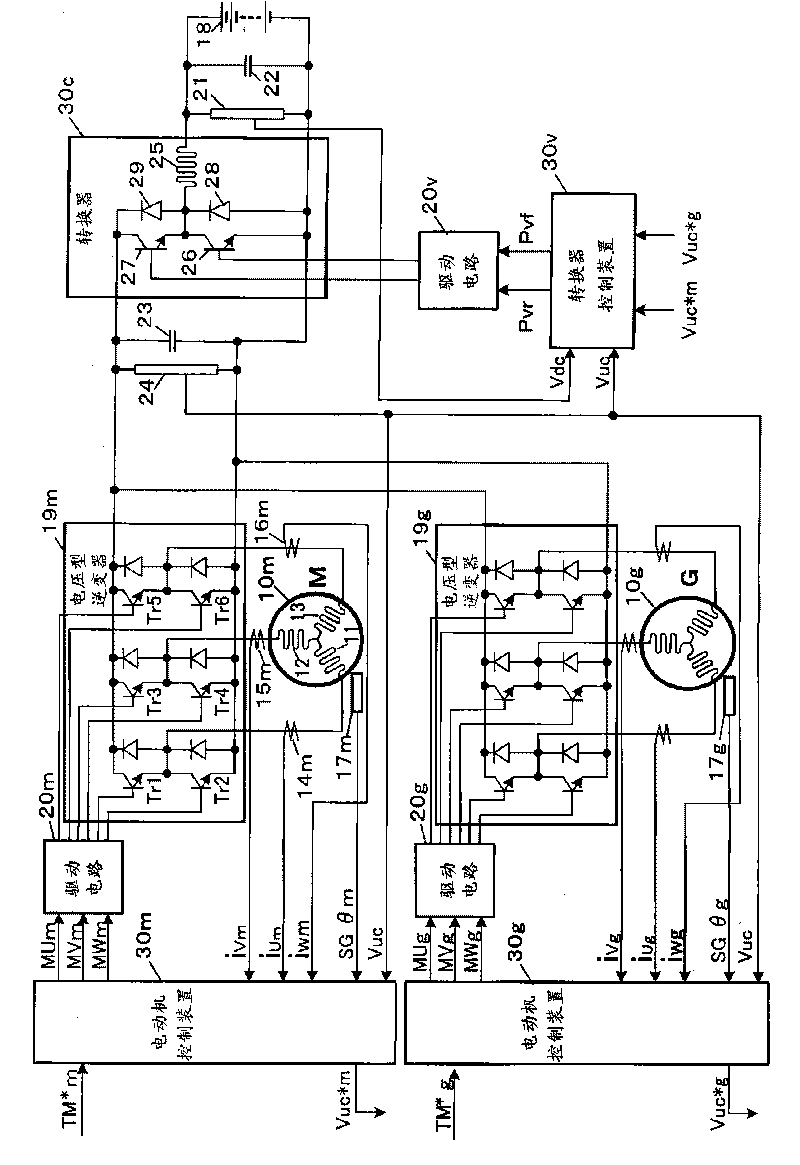
[0074] figure 1 The outline of the first embodiment of the present invention is shown. The electric motor 10m as the motor to be controlled is, in this embodiment, a permanent magnet synchronous motor for rotationally driving the wheels mounted on the vehicle. A permanent magnet is built into the rotor, and U-phase, V-phase, and The three-phase coils 11 to 13 of the W phase. The voltage source inverter 19m supplies electric power of the battery 18 on the vehicle to the electric motor 10m. A rotor of a resolver 17m for detecting the magnetic pole position of the rotor is connected to the rotor of the motor 10m. The resolver 17m generates an analog voltage (rotation angle signal) SGθm indicating the rotation angle of the motor, and applies it to the motor control device 30m.

[0075] A primary-side capacitor 22 is connected to the battery 18 serving as a storage battery of the vehicle when the power supply of the electric parts of the vehicle is turned on, and constitutes a ...


PUM


Abstract

When driving a motor, a primary side DC voltage is boosted to a secondary voltage by a converter (30c) and the voltage is converted into a 3-phase AC by an inverter (19) for supply to the motor (10m). A regeneration power of the motor is supplied to primary DC power sources (18, 21) via an inverse route. A secondary side target voltage which defines the secondary voltage to be applied to the inverter is decided according one of the following three regions: a first region where the motor is driven in a modulation mode for PWM electrical connection to at least two phases and weak field control is not performed; a third region where weak field control is performed in the modulation mode for PWM electric communication to at least two phases with a voltage smaller than a maximum voltage (Vmax) of the converter; and a second region where weak field control is performed in a 1-pulse mode for rectangular-wave electrical communication of all the phases with a voltage smaller than the maximum voltage of the converter. A converter control device (30v) decides the secondary voltage to be the secondary side target voltage.

Description

technical field [0001] The present invention relates to a motor control device for controlling the power supplied from an inverter to a motor and the regenerative power in the reverse direction thereof, and particularly relates to the control of the operating voltage applied to the motor by the inverter and the voltage control mode. The motor control device of the present invention can be used, for example, in an electric vehicle (EV) whose wheels are driven by an electric motor, and which has, in addition to the electric motor, a fuel engine and a generator (also referred to as an electric motor or generator) rotationally driven by the engine. ) of hybrid electric vehicles (HEV). Background technique [0002] As the rotation speed of the motor increases, the counter electromotive force generated in the stator coil increases, thereby making it difficult to supply a target current from the inverter to the stator coil, and a target torque output cannot be obtained. In this ca...

Claims


Application Information

Patent Timeline
IPC IPC(8): H02P21/00H02P27/04H02P27/06H02P27/08H02M3/155B60L3/00B60L9/18B60L50/16H02P6/06H02P6/08H02P6/17H02P6/28
CPCB60L2240/423Y02T10/643H02P21/0089B60L2210/12B60L15/08Y02T10/7241Y02T10/7233B60L2210/14Y02T90/16B60L2240/421Y02T10/642B60L15/025B60L2210/42Y02T10/7225Y02T10/64Y02T10/72B60L7/10H02P3/14
Inventor 苏布拉塔·萨哈吉田高志荻野大介伊泽仁大野佳纪
Owner AISIN AW CO LTD
Why Eureka
Try Eureka