Eureka AIR delivers breakthrough ideas for toughest innovation challenges, trusted by R&D personnel around the world.

Unsupported alternating curved tube dry type evaporator

A dry evaporator and variable surface technology, applied in evaporators/condensers, tubular elements, heat exchange equipment, etc., can solve the problems of large flow resistance in the tube, reduced heat exchange efficiency, and large boundary layer thermal resistance. The effect of uniform flow distribution and flow velocity, increased effective heat transfer area, and reduced shell side pressure drop

Inactive Publication Date: 2010-06-30
SOUTH CHINA UNIV OF TECH
View PDF0 Cites 10 Cited by
  • Summary
  • Abstract
  • Description
  • Claims
  • Application Information

AI Technical Summary

Problems solved by technology

However, this shell-and-tube heat exchanger also has some shortcomings, mainly: first, the heat exchange tube adopts a round tube, and under the condition of low flow rate in the tube, the thermal resistance of the boundary layer is large and the heat transfer coefficient is low; However, under the condition of high flow rate, the flow resistance in the pipe is relatively large.
Second, the traditional single-bow baffle heat exchanger has a flow dead zone at the junction of the baffle and the shell, which easily causes the fluid to swirl, increases the flow resistance, and easily causes fouling, reducing the heat exchange efficiency
Third, the traditional single-bow baffle is difficult to cooperate with non-circular enhanced heat transfer tubes, which greatly limits the application of enhanced heat transfer technology
These problems have seriously affected the heat transfer efficiency of the traditional dry evaporator. In order to improve its efficiency, people have continuously improved its structure, but the results are not satisfactory.

Method used


Image

  • Unsupported alternating curved tube dry type evaporator
  • Unsupported alternating curved tube dry type evaporator
  • Unsupported alternating curved tube dry type evaporator

Examples


Embodiment Construction

[0020] In order to further understand the present invention, the present invention will be further described below in conjunction with the accompanying drawings. It should be noted that the specific embodiments do not limit the protection scope of the present invention.

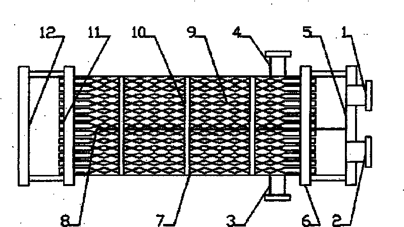
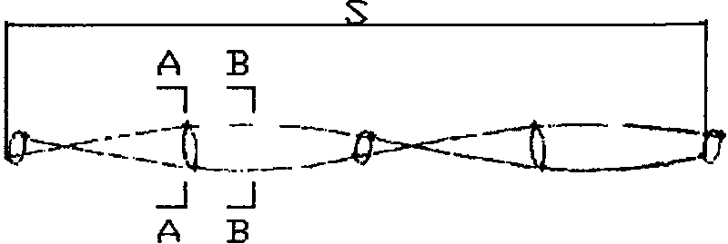
[0021] refer to figure 1 , an unsupported alternating surface tube dry-type evaporator includes a refrigerant inlet 1, a refrigerant outlet 2, a chilled water inlet 3, a chilled water outlet 4, a first head 5, a second head 12, a first tube sheet 6, The second tube sheet 11, the shell 7, the partition plate 8, the heat exchange tube 9 and the binding steel strip 10; The plate 6 and the second tube sheet 11, the first tube sheet 6 and the second tube sheet 11 are respectively connected with the first head 5 and the second head 12 to form a cavity; the refrigerant inlet 1 and the refrigerant outlet 2 are both arranged at the first On the head 5, it is separated by a partition 8. Such as image 3 As shown, th...


PUM


Abstract

The invention discloses an unsupported alternating curved tube dry type evaporator, which comprises a refrigerant inlet, a refrigerant outlet, a chilled water inlet, a chilled water outlet, a first end socket, a second end socket, a first tube sheet, a second tube sheet, a shell, a clapboard, heat exchange tubes and a bundling steel belt, wherein the heat exchange tubes are alternating curved tubes, and a ratio of the twist range and the equivalent diameter of each heat exchange tube is 6-12; the ratio of the short shaft and the long shaft of the cross section of the heat exchange tube 9 is 0.5-0.7; and the alternating curved heat exchange tubes are sequentially contacted with each other to be arranged, and are supported by self to form tube bundles depending on each contact point of the alternating curved tubes. The invention strengthens the turbulence degree of fluid in the tubes so that the fluid in the tubes can be fully mixed and the boundary layer is reduced, and strengthens the heat transfer. A shell side is not provided with baffles and can realize self supporting depending on the mutual contact of the alternating curved tubes, the fluid flows among the tubes are uniform, flow dead zones are eliminated, fouling deposit of the shell side is reduced, the heat transfer efficiency is improved, the service life of equipment is prolonged, and production cost is lowered.

Description

technical field [0001] The invention relates to a dry evaporator, in particular to a dry evaporator with alternating curved surface tubes without support for tube bundles. Background technique [0002] In large and medium-sized chillers, the most important form of heat exchanger is the shell and tube heat exchanger. There are two main types of shell and tube heat exchangers: dry type and flooded type. Flooded heat exchangers are becoming more and more popular due to their high heat exchanger performance, but their fatal disadvantage is the oil return problem of the unit, which increases the cost of the unit on the one hand, and reduces the reliability of the unit on the other hand. sex. The technology of dry evaporators is much more mature than that of flooded evaporators. The traditional dry evaporator is still the most widely used heat exchanger in the industry at present. One of its important features is that the baffle is set on the shell side to support the heat exch...

Claims


Application Information

Patent Timeline
IPC IPC(8): F25B39/02F28F1/08
Inventor 朱冬生刘庆亮徐琼辉杨蕾
Owner SOUTH CHINA UNIV OF TECH
Why Eureka
Eureka Blog
Learn More