Fuel washing device for aircraft refueling vehicle

A technology of aircraft refueling and washing equipment, which is applied in the direction of fuel tank safety measures, etc., which can solve the problems of unfavorable flight of aircraft, increase of equipment size and weight, and limited time, and achieve the effect of even distribution of washing gas

Inactive Publication Date: 2010-07-07
NANJING UNIV OF AERONAUTICS & ASTRONAUTICS
View PDF0 Cites 7 Cited by
  • Summary
  • Abstract
  • Description
  • Claims
  • Application Information

AI Technical Summary

Problems solved by technology

[0010] For some aircraft, such as fighter jets, when performing many tasks, from refueling, warming up, taxiing, climbing, until the beginning of combat missions, its time is extremely limited. In order to make the fuel wash to a suitable oxygen content, It is necessary to increase the amount of scrubbing gas, which will obviously further increase the size and weight of the equipment, which is very detrimental to the flight of the aircraft

Method used


Image

  • Fuel washing device for aircraft refueling vehicle
  • Fuel washing device for aircraft refueling vehicle
  • Fuel washing device for aircraft refueling vehicle

Examples


Embodiment 1

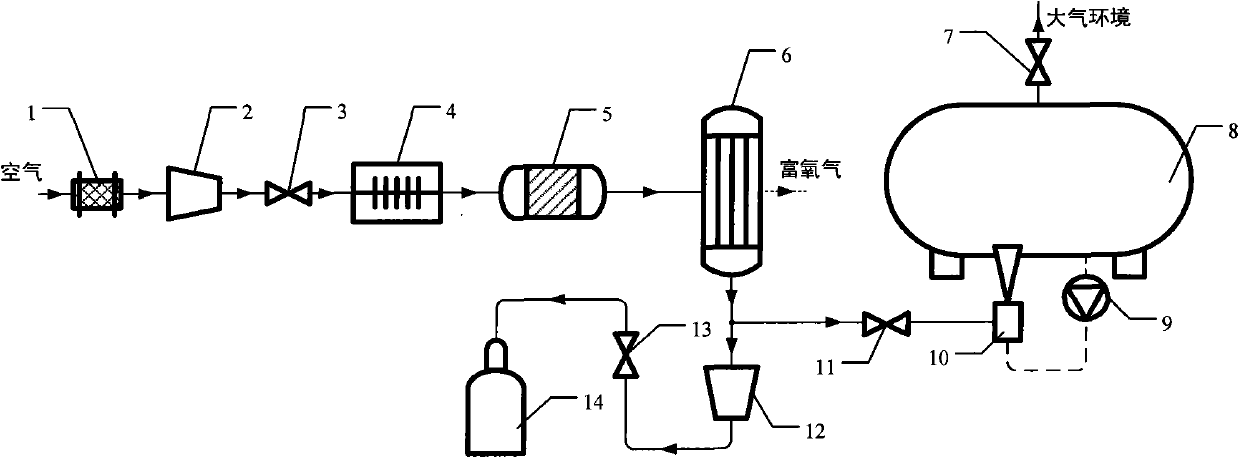
[0034] Such as figure 1 , image 3 and Figure 4 As shown, the aircraft refueling vehicle fuel washing device of the present invention includes a nitrogen-enriched gas generating device, a fuel circulation pump 9, a gas-oil mixing device and a refueling vehicle oil tank 8, wherein:

[0035]The gas-oil mixing device is respectively provided with an air inlet, an oil inlet hole and an output hole, and the gas-oil mixing device is composed of more than one washing nozzle 10, and the output hole of each washing nozzle 10, that is, the installation position of the nozzle opening is low. The lowest fuel level in the oil tank 8 of the refueling truck is used to ensure the safety and reliability of fuel washing in the fuel tank 8 of the refueling truck;

[0036] The nitrogen-enriched gas generating device comprises an air compressor 2, a nitrogen-enriched gas generator 6 and a heat exchanger 4 connected between the air outlet of the air compressor 2 and the air inlet 23 of the nitro...

Embodiment 2

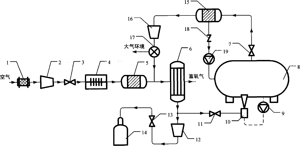
[0043] This embodiment is basically the same as Embodiment 1, the difference being that the outlet of the scrubbing exhaust valve 7 is connected to the exhaust gas recovery device through a gas delivery pipe, and the exhaust gas recovery device includes a scrubbing exhaust gas treatment unit 15, a scrubbing exhaust gas compressor 16 and fuel oil Recovery pump 19, the exhaust gas treatment unit 15 is a gas-oil separation device, the exhaust gas treatment unit 15 is provided with an oil outlet and an air outlet respectively, and the exhaust gas outlet of the exhaust gas treatment unit 15 passes through the oil delivery pipe and the fuel recovery pump 19 is connected to the liquid inlet hole, while the oil outlet hole of the fuel recovery pump 19 is connected to the oil tank 8 of the refueling vehicle, and a check valve 18 is connected to the oil delivery pipe between the exhaust gas treatment unit 15 and the fuel recovery pump 19. The air outlet of the unit 15 is connected with t...


PUM


Abstract

The invention relates to a fuel washing device for an aircraft refueling vehicle, which comprises a nitrogen-rich gas generating device, a fuel circulating pump, a gas and fuel mixing device and a fuel tank of the refueling vehicle. A nitrogen-rich gas outlet of the nitrogen-rich gas generating device is connected with a gas inlet of the gas and fuel mixing device through a gas delivering pipe. The gas delivering pipe between the nitrogen-rich gas outlet of the nitrogen-rich gas generating device and the gas inlet of the gas and fuel mixing device is connected with a washing check valve. The fuel circulating pump is connected with a fuel inlet hole of the gas and fuel mixing device through a fuel conveying pipe, and an outlet hole of the gas and fuel mixing device is connected with the fuel tank of the refueling vehicle. A gas exhaust opening of the fuel tank of the refueling vehicle is connected with a washing gas exhaust valve. When the device is used for performing fuel washing on the fuel tank of the refueling vehicle in fuel delivery, the device effectively overcomes the technical defects of the airborne nitrogen generating system, has no need of taking the weight and volume of the equipment into consideration, and can use large separating film area and high separating pressure to obtain nitrogen-rich gas with large flow quantity and high purity for washing.

Description

technical field [0001] The invention belongs to the technical field of fire protection and explosion protection, and relates to an aircraft fuel washing device, in particular to a fuel washing device for an aircraft refueling vehicle. Background technique [0002] With the improvement of the flight speed and performance of aircraft, the increase of aerodynamic heating and heat load of electronic equipment brought about by it makes modern military aircraft generally tend to adopt fuel integrated thermal management technology. Simply put, fuel oil is used as a heat sink. For military aircraft, according to statistics, even if fuel oil is not used as a heat sink, the fire or explosion of its fuel system has become one of the main causes of its crash. And when the comprehensive fuel thermal management technology is adopted, it will further increase the temperature of the aircraft fuel tank, that is to say, it will also increase the probability of the aircraft fuel tank catching...

Claims


Application Information

Patent Timeline
Patent Type & Authority Applications(China)
IPC IPC(8): B64D37/32
Inventor 冯诗愚刘卫华高秀峰刘小芳鹿世化
Owner NANJING UNIV OF AERONAUTICS & ASTRONAUTICS
Why Eureka
Try Eureka