High-efficiency mixer igniter used for pulse soot blower

A soot blower and mixing point technology, applied in the field of high-efficiency mixing igniters, can solve the problems of poor mixing uniformity of the mixer, and achieve the effect of improved mixing uniformity, high mixing uniformity, and exquisite design

Inactive Publication Date: 2010-07-07
BEIJING FANYUANXING SCI & TECH +1
View PDF0 Cites 2 Cited by
  • Summary
  • Abstract
  • Description
  • Claims
  • Application Information

AI Technical Summary

Problems solved by technology

[0003] Existing explosive wave sootblowers all use air as the combustion-supporting gas, and most of the fuel is gaseous fuel. Therefore, it is necessary to put fuel gas and air in a s

Method used


Image

  • High-efficiency mixer igniter used for pulse soot blower
  • High-efficiency mixer igniter used for pulse soot blower

Examples


Embodiment Construction

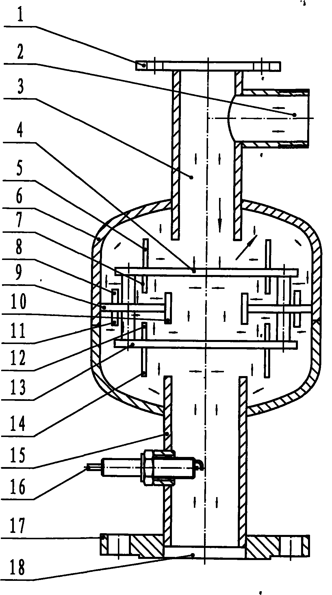
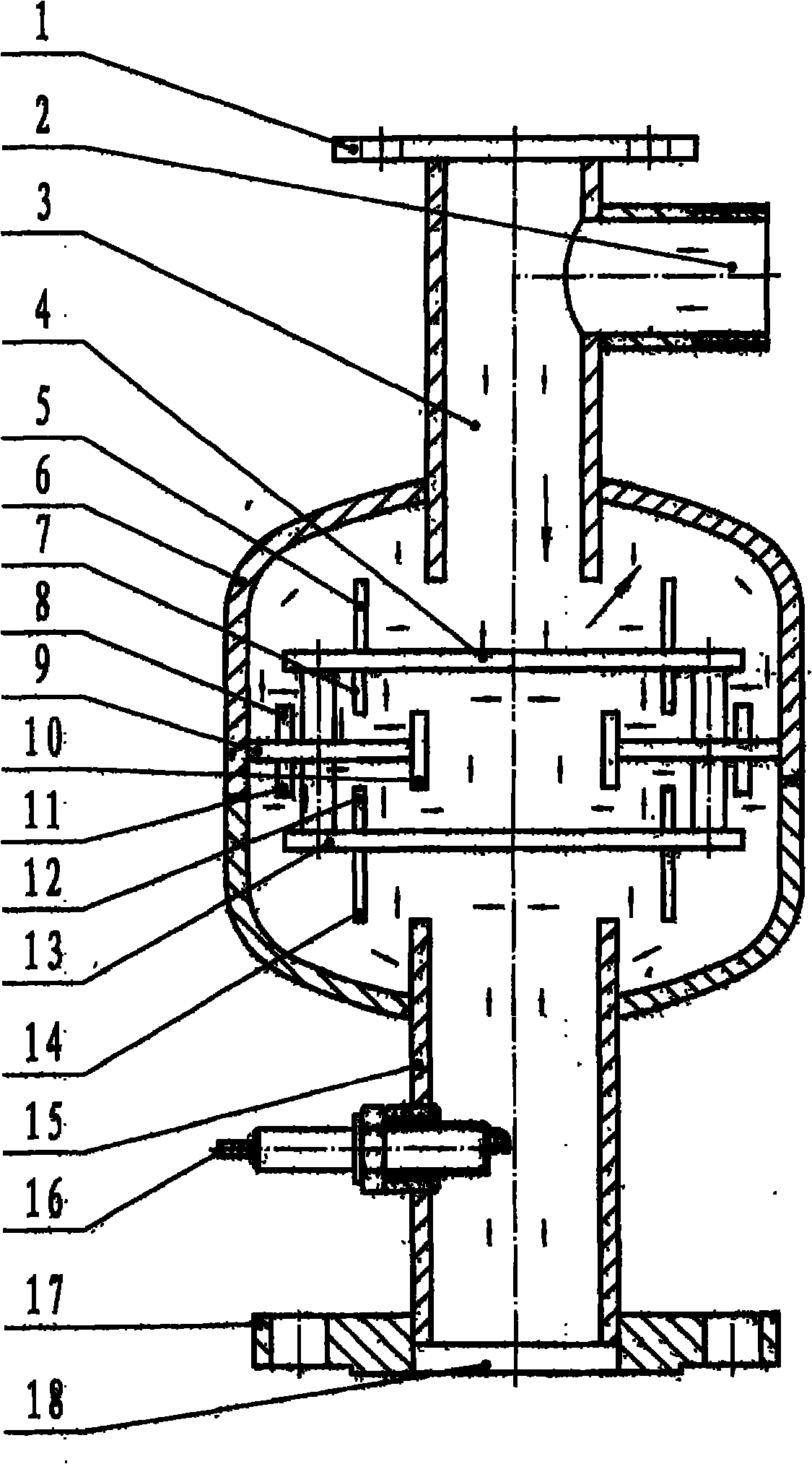
[0014] Fuel gas and air are in the state of laminar flow, first hit the upper splitter baffle (4) through the air inlet (2), the gas disperses around and hits the inlet upper retaining ring (5), and hits the upper casing (6) upwards , hits the collector baffle (9) downward, flows inward and hits the inlet lower retaining ring (7), then hits the collector baffle (9) downward, flows inward and hits the gas collector (10), and hits again The upper diverter baffle (4), when the gas flows towards the center, the gas collides with each other; when it hits the lower diverter baffle (12) downward, the gas disperses and hits the upper retaining ring of the outlet (11), and the gas hits the collector upwards Baffle (9), the gas hits the collector baffle (4) upwards, and hits the shell (3) outwards, the gas hits the outer diameter of the upper end of the outlet pipe (15) along the shell, and the gas hits the upper end of the outlet pipe (15) upwards When the lower diverter baffle reaches...


PUM


Abstract

Disclosed is a high-efficiency mixer igniter which is used for a pulse soot blower, comprising a positioning end cover (1), a gas inlet pipe (2), a gas inlet pipeline (3), an upper distributing baffle (4), an inlet upper shield ring (5), an outer shell (6), an inlet lower shield ring (7), a shield ring (8), an affluence baffle (9), a gas collector (10), a shield ring (11), an outlet upper shield ring (12), a lower distributing baffle (13), an outlet lower shield ring (14), a gas outlet pipe (15), an igniter (16), a connection flange (17), a fuel gas outlet (18), and a mixer and the igniter are combined in a whole. The air inlet pipeline (3) and the gas collector (10) are arranged to form two channels which shatter airflow from the center to the surrounding when the airflow passes through and respectively impacts the upper damper (4) and the lower damper (13). Two ring airflow channels which are formed by the upper baffle (4) and the lower baffle (13) as well as the outer shell (6) are arranged. Two airflow channels of the gas collector (10) and the gas outlet pipe (15) have two airflow channels capable of driving air flow to flow to the center in centralization manner. The air inlet pipe (2) is connected by pipe threads, and the mixed air outlet (18) is connected by the flange. The installation positioning is positioned by the positioning end cover (1) and the flange (17).

Description

Technical field [0001] The invention belongs to the technical field of boiler pulse soot blowing, and in particular relates to a high-efficiency mixing igniter for pulse soot blowers. Background technique [0002] The pulse soot blower, also known as the explosion wave soot blower, was first proposed by Ukrainian scientists in the 1980s. It mainly makes the premixed gas formed by fuel and combustion-supporting gas communicate with the flue through the nozzle. Combustion and explosion in the explosion tank, through the impact of the explosion shock wave and the scouring effect of the high-speed jet, the dust accumulation on the heat exchange surface and the wall of the flue is removed. Domestically, it has been developing since the 1990s. Due to the good cleaning effect and the ability to remove stubborn dirt, it has developed very rapidly. [0003] Existing explosive wave sootblowers all use air as the combustion-supporting gas, and most of the fuel is gaseous fuel. Therefo...

Claims


Application Information

Patent Timeline
IPC IPC(8): F23R7/00F23J1/00F23J3/00
Inventor 王海超
Owner BEIJING FANYUANXING SCI & TECH
Why Eureka
Try Eureka