
Switched reluctance motor flux linkage characteristic measurement method

A switched reluctance motor and measurement method technology, applied in the direction of the magnitude/direction of the magnetic field, can solve the problems of less use, influence on measurement results, expensive software, etc., and achieve the effect of easy acquisition, simple measurement and calculation process

Inactive Publication Date: 2010-07-07
NANTONG UNIVERSITY
View PDF0 Cites 17 Cited by
  • Summary
  • Abstract
  • Description
  • Claims
  • Application Information

AI Technical Summary

Problems solved by technology

However, specialized software is expensive, and users of switched reluctance motor design data are often not available
On the other hand, the calculation process of finite element is very time-consuming, and the accuracy of the calculation results depends to a large extent on the specific division of the finite element grid
[0005] (2) Direct measurement method: The direct measurement method is to measure the magnetic flux density with the help of a magnetic sensor installed inside the motor to obtain the flux linkage. Because this method is inconvenient and expensive, it is rarely used in practice.
Most of the indirect detection methods require special rotor mechanical positioning and clamping devices, and when the electromagnetic torque is large during the measurement process, the rotor will rotate to a certain extent, which affects the measurement results

Method used


Image

  • Switched reluctance motor flux linkage characteristic measurement method
  • Switched reluctance motor flux linkage characteristic measurement method
  • Switched reluctance motor flux linkage characteristic measurement method

Examples


Embodiment Construction

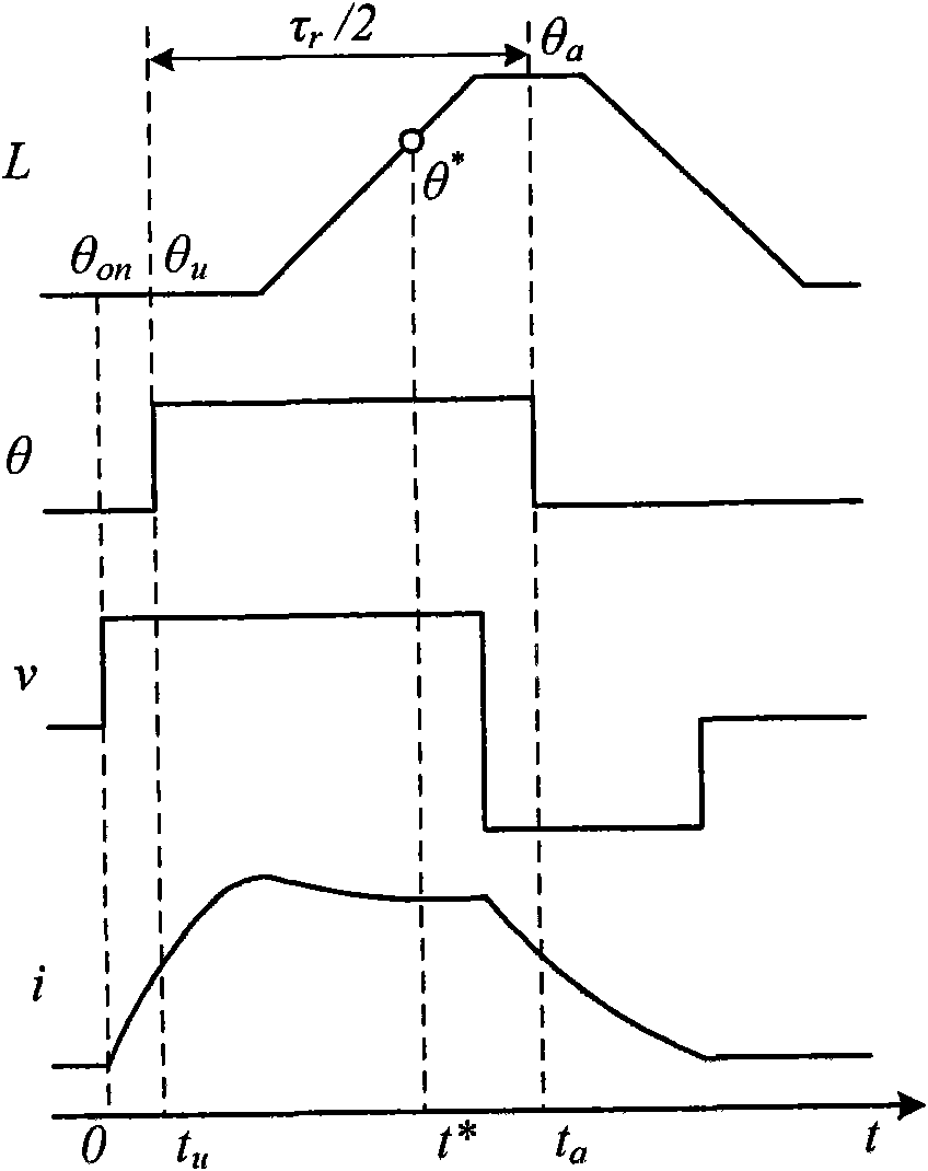
[0024] The frame diagram of this method is as follows figure 1 As shown, it consists of a commonly used switched reluctance motor speed control system and a digital storage oscilloscope. In order to obtain the flux linkage value, it is necessary to make the SRD run in a steady state, and then measure the voltage u, current i, and position angle θ of a certain phase. Since the parameters of each phase of the motor are the same, any phase can be used as the measurement phase. The measured u, i, θ and sampling time t are given by The matrix form of is stored in DSO, where are column vectors. By adjusting the operating parameters of the SRD, sample data groups with different experimental requirements attributes can be measured and stored. After obtaining these data, the flux linkage can be calculated on the PC according to the algorithm mentioned below on the basis of these data.

[0025] The relationship between the inductance L and the measured signal (θ, u, i) is as fo...


PUM


Abstract

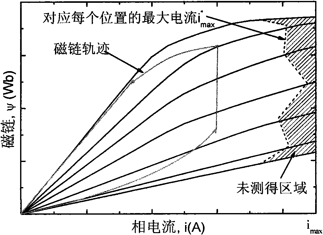
The invention discloses a switched reluctance motor flux linkage characteristic measurement method, which includes the following steps: a position sensor is calibrated, and the coefficient of a measuring circuit is determined; a load is removed, a switched reluctance motor is operated, and the switching angle is adjusted, so that the phase current of the motor is similar to the shape of a flat-topped wave; the direct-current voltage is decreased, so that the peak value of the phase current is as small as possible, and a data matrix is sampled and stored; the direct-current voltage is increased, so that the peak value of the phase current is slowly increased; the load is added, the turn-on angle or the turn-off angle is changed, a needed data set is detected, and the data are sampled and stored; and the peak value of the current is gradually increased until reaching the upper limit of the current allowed by the motor, and data vectors are recorded under different currents until the maximum phase current reaches a maximum current imax needing a current peak value. The whole process of the method only uses the conventional switched reluctance motor speed regulation system and the conventional storage type digital oscilloscope, and does not need a specialized mechanical rotor positioning and clamping device, and the measuring equipment can be easily obtained.

Description

Technical field: [0001] The invention relates to a method for measuring the flux linkage characteristic of a switched reluctance motor. Background technique: [0002] Flux linkage characteristics are the basis of research on modeling, simulation and model-based control of switched reluctance motors. The function of the flux linkage of each phase with respect to the phase current and position angle can be expressed as ψ(i, θ). Due to the double salient pole structure and the saturation nature of the magnetic circuit of the switched reluctance motor, the flux linkage presents a highly nonlinear characteristic, which is accurate It is also difficult to describe the ψ(i, θ) function. [0003] The literature proposes a variety of methods to obtain the flux linkage characteristics of switched reluctance motors. These methods can be divided into finite element method (FEA), direct measurement method and indirect measurement method. [0004] (1) Finite element method: Flux linkag...

Claims


Application Information

Patent Timeline
IPC IPC(8): G01R33/02
Inventor 陈海进樊宁佳罗向东景为平
Owner NANTONG UNIVERSITY
Learn More