Linear beam shaping optical system

A beam shaping, optical system technology, applied in optics, optical components, installation, etc., can solve problems such as uneven distribution

Inactive Publication Date: 2010-07-07
WUHAN LINGYUN PHOTOELECTRONICS SYST
View PDF0 Cites 25 Cited by
  • Summary
  • Abstract
  • Description
  • Claims
  • Application Information

AI Technical Summary

Problems solved by technology

[0003] The problem to be solved by the present invention is: when the laser beam passes through a cylindrical lens or a Powell prism, the energy distribution of the linear beam formed by it has uneven distribution in the middle and the edge.

Method used


Image

  • Linear beam shaping optical system
  • Linear beam shaping optical system
  • Linear beam shaping optical system

Examples


Embodiment Construction

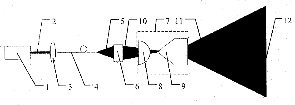
[0015] The present invention combines the attached figure 1 , its technical scheme is described in detail as follows:

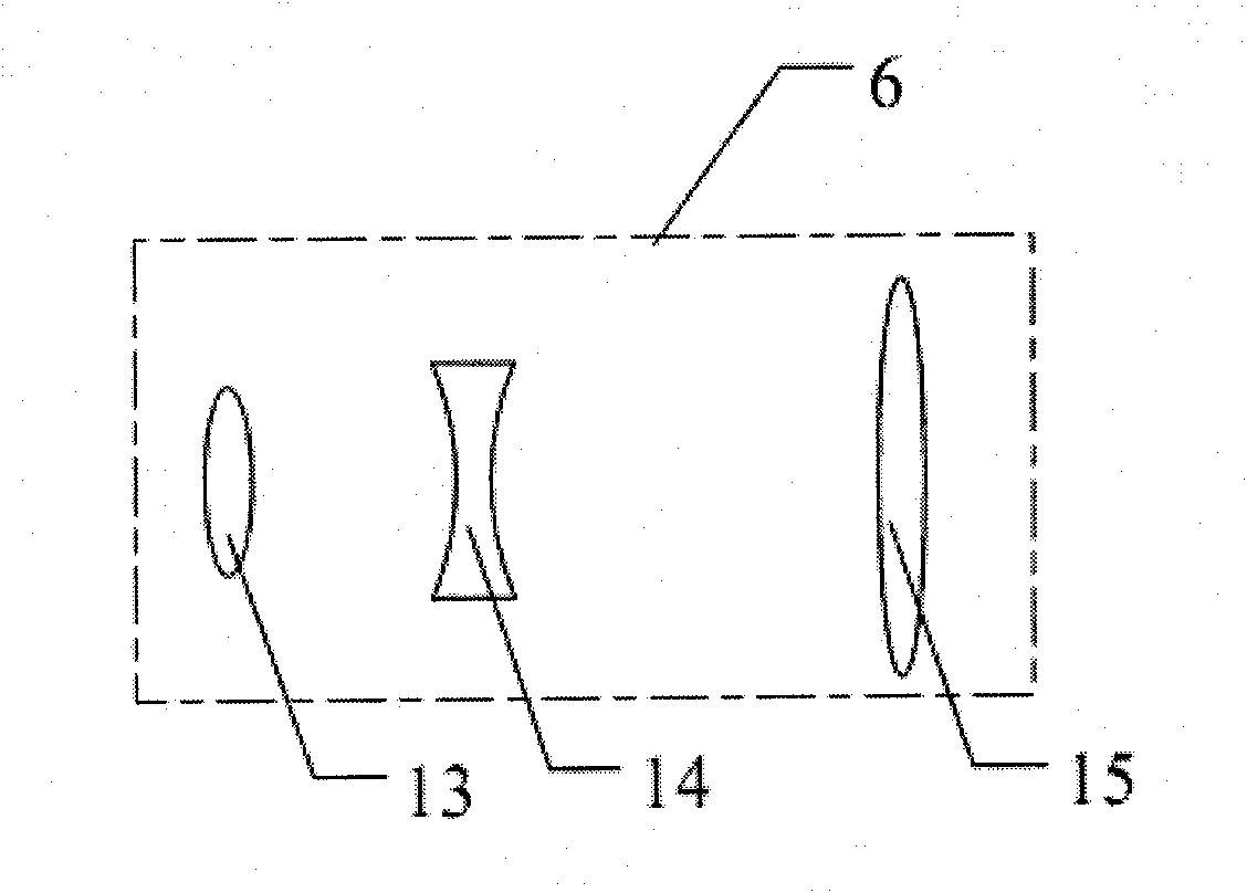
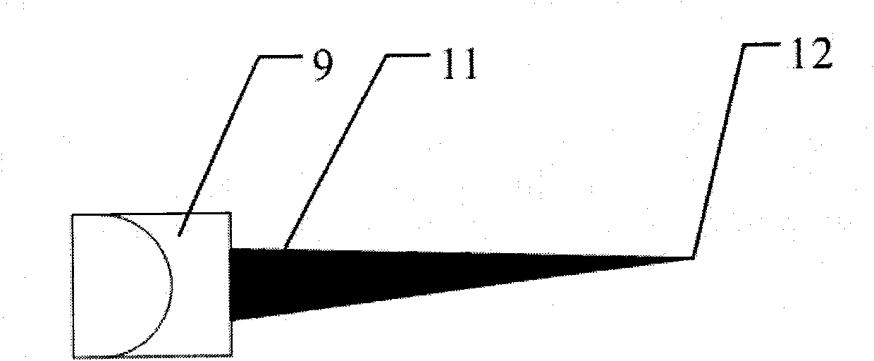
[0016] A linear beam shaping optical system, including a laser source 1, the laser source 1 radiates laser 2, the power of the laser 2 is 30W, the wavelength of the laser 2 is 808nm, the laser 2 is coupled to the optical fiber 4 through the optical fiber coupling system 3, the optical fiber 4 has a core diameter of 200 microns. After the laser 2 is transmitted through the optical fiber 4, it forms a beam 5 with a relatively uniform energy distribution. The beam 5 is incident on the beam focusing system 6. The beam shaping system 7; the linear beam shaping system 7 includes a cylindrical mirror 8 (the focal length of the cylindrical mirror is f=45mm) and an improved Powell prism 9 (the included angle of the roof surface is 70°). After the laser beam 5 passes through the focusing system 6, a converging beam 10 is formed. The converging beam 10 passes through t...


PUM

PropertyMeasurementUnit
diameteraaaaaaaaaa

Abstract

The invention relates to a linear beam shaping optical system, comprising a laser light source, an optical fiber coupling system, a transmission optical fiber, and a spherical surface lens set. The characteristics are as follows: the laser emitted from the light source enters the optical fiber through the fiber coupling system, is transmitted by the optical fiber, and is incident to the spherical surface lens set; the light beam outgoing from the spherical surface lens set passes through a cylindrical mirror and an improved Powell prism to form a broom-shaped beam in space, lastly, a linear light beam with evenly-distributed energy is formed at vertical focus point. The invention can effectively overcome the defect of uneven energy of the linear light beam caused by ordinary cylindrical mirror imaging and ordinary Powell prism imaging. The adoption of optical fiber transmission can separate the laser from the light beam shaping system and increase the stability, thereby providing needed light beam for track traffic, road test. The invention not only can be widely used for the linear light beam system needed by track traffic, road test, but also can be used for surveying and mapping of building and other application occasions.

Description

technical field [0001] The invention relates to a shaping optical system, in particular to a linear light beam shaping optical system. Background technique [0002] Scientific engineering applications such as construction engineering, road surveying, rail traffic monitoring, etc. all require a suitable linear laser beam as a light source. Degree and line width indicators, the laser energy distribution should be relatively uniform. Usually, when the laser beam passes through a cylindrical lens or a common Powell prism, the cylindrical lens or Powell prism can expand the laser beam in one direction to form a linear beam, and the linear beam formed by the cylindrical lens has intermediate energy. The distribution is higher and the edge energy distribution is lower. The Powell prism is the opposite. The energy distribution of the linear beam formed by it has the characteristics of weak middle and strong edge. Contents of the invention [0003] The problem to be solved by the...

Claims


Application Information

Patent Timeline
Patent Type & Authority Applications(China)
IPC IPC(8): G02B27/09G02B7/02G02B7/18
Inventor 夏文建王锋
Owner WUHAN LINGYUN PHOTOELECTRONICS SYST
Why Eureka
Try Eureka