
Method and equipment for synchronous removal of carbon, nitrogen and sulfur

A technology for removing carbon and nitrogen, applied in the field of water treatment, can solve the problems of low conversion rate of elemental sulfur, low treatment efficiency, poor operability, etc., and achieve the effect of low operating cost, high treatment efficiency and easy operation

Inactive Publication Date: 2010-07-14
HARBIN INST OF TECH
View PDF1 Cites 10 Cited by
  • Summary
  • Abstract
  • Description
  • Claims
  • Application Information

AI Technical Summary

Problems solved by technology

[0003] The purpose of the present invention is to solve the problems of complex process, low treatment efficiency, poor operability and low conversion rate of elemental sulfur in the existing method for synchronous removal of carbon, nitrogen and sulfur, and to provide a carbon and nitrogen Method and equipment for synchronous removal of sulfur

Method used

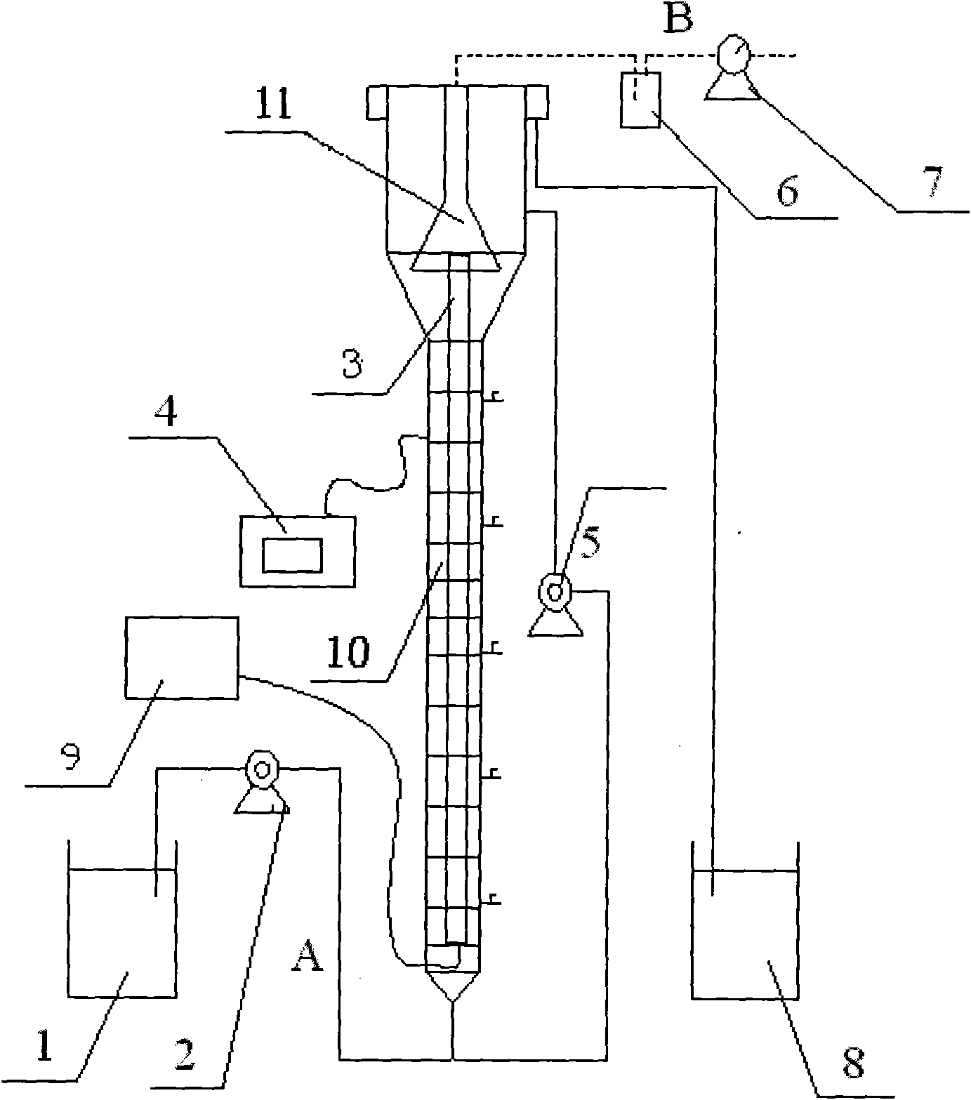
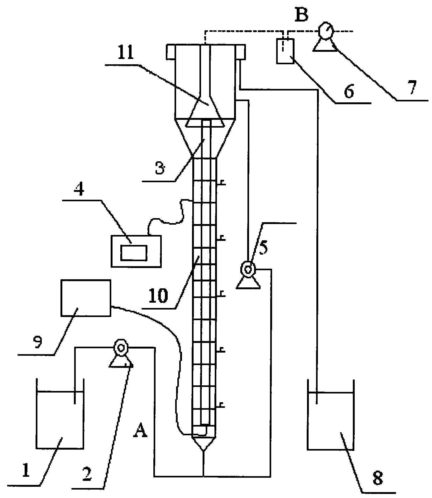

Image

  • Method and equipment for synchronous removal of carbon, nitrogen and sulfur
  • Method and equipment for synchronous removal of carbon, nitrogen and sulfur
  • Method and equipment for synchronous removal of carbon, nitrogen and sulfur

Examples


specific Embodiment approach 1

[0018] Specific embodiment one: the method for synchronous removal of carbon, nitrogen and sulfur in this embodiment is carried out according to the following steps: the activated sludge is added to the equipment for synchronous removal of carbon, nitrogen and sulfur, and then the waste water to be treated is passed into, and the ratio of sulfur to nitrogen is controlled to be 2-5:1, the carbon-sulfur ratio is 1.2-3:1, add 0.5-2mL trace element solution to each liter of wastewater, control the temperature of the carbon, nitrogen and sulfur synchronous removal equipment to 27-29°C, and the pH to 7.5 ~8.3, the concentration of dissolved oxygen is 0~0.4mg / L, SO 4 2- -S volume load is 1.80~1.90kg / m 3 d, NO 3 - The volume load of N is 0.60~0.70kg / m 3 d, the aeration rate is 5-35mL / min, and the hydraulic retention time is 34-38 hours, which realizes the simultaneous removal of carbon, nitrogen and sulfur.

[0019] In the method for simultaneous removal of carbon, nitrogen and s...

specific Embodiment approach 2

[0021] Specific embodiment two: the difference between this embodiment and specific embodiment one is that every liter of trace element solution is composed of 500 mg of H 3 BO 3 , 500mg of ZnCl 2 , 500mg of (NH 4 ) 6 Mo 7 o 24 4H 2 O, 500mg of NiCl·6H 2 O, 500mg of AlCl 3 ·6H 2 O, 500mg of CoCl 2 ·6H 2 O, 500mg of CuSO 4 ·5H 2 O, 1000mg of NaSeO 3 ·5H 2 O, 1500mg of FeCl 3 ·6H 2 O, 5000mg of MnCl 2 4H 2 O and 5 ml of a 37% HCl solution. Other steps and parameters are the same as those in the first embodiment.

specific Embodiment approach 3

[0022] Embodiment 3: This embodiment differs from Embodiments 1 to 2 in that the ratio of sulfur to nitrogen is 5:1, and the ratio of carbon to sulfur is 1.26:1. Other steps and parameters are the same as those in Embodiments 1 to 2.


PUM


Abstract

The invention discloses a method and equipment for synchronous removal of carbon, nitrogen and sulfur, relating to a water treatment method and equipment thereof. The invention solves the problem of complex process, low processing efficiency, poor operability and low elemental sulfur conversion rate which easily leads to secondary pollution in the existing method for synchronous removal of carbon, nitrogen and sulfur. The method is as follows: adding active sludge into the equipment used for synchronous removal of carbon, nitrogen and sulfur, and controlling the temperature of the equipment, pH, and concentration of dissolved oxygen, the volume load of elemental sulfur, the volume load of NO3-N, the aeration rate and the hydraulic retention time. In this way, the carbon, nitrogen and sulfur can be removed synchronously. The equipment comprises a fluidized bed reactor, a gas flowmeter, a tapered gas collecting hood, an aeration pump and a microporous aeration strip. With the method, the efficiency is high, the conversion rate of the elemental sulfur is high, the problem of secondary pollution easily caused by low elemental sulfur conversion rate is solved, the process is simple and easy to control and the operating cost is low.

Description

technical field [0001] The invention relates to a water treatment method and equipment thereof. Background technique [0002] With the rapid development of petrochemical, pharmaceutical, food fermentation, papermaking and other industries, the pollution of organic wastewater containing sulfur and nitrogen is becoming more and more serious. Finding an effective wastewater treatment process has long been a common concern in the field of environmental engineering. At present, for sulfate and ammonia nitrogen in high-concentration organic wastewater, separate treatment strategies are usually adopted, and the respective treatment processes are carried out in two steps, that is, sulfate is reduced to sulfide and then oxidized to elemental sulfur, ammonia nitrogen is oxidized to nitrate and then processed. Denitrification into nitrogen, the process is complicated, the operability is poor and the treatment efficiency is not high. Another integrated method for synchronous removal o...

Claims


Application Information

Patent Timeline
IPC IPC(8): C02F3/30C02F1/58
Inventor 王爱杰张莉任南琪陈川周旭徐熙俊刘充高灵芳许继飞李笃中
Owner HARBIN INST OF TECH
Learn More