Piston-type direct-drive engine and design method for first taking force and then integrating

An engine and piston-type technology, which is applied in the field of piston direct-drive engines, can solve the problems that the engine cannot be reversely driven by external force, the gear shaft cannot be strong, and the engine has a short service life. energy effect

Inactive Publication Date: 2010-07-14
HAIMEN THE YELLOW SEA ENTREPRENEURSHIP PARK SERVICE CO LTD
View PDF3 Cites 4 Cited by
  • Summary
  • Abstract
  • Description
  • Claims
  • Application Information

AI Technical Summary

Problems solved by technology

The technologies disclosed in the above documents are all opposed-piston direct-drive engines, and the core issue discussed is how to take power. For example, the patent No. 01120523.7 uses two one-way gears with ratchets and a double-sided rack connected to the pistons. Engagement outputs a force in one direction of rotation. The piston engine of "Patent No. 94238030.4" uses a half-gear to mesh with the rack to take out force; The force rotating in the same direction can do work externally, but the engine cannot be started in a static state through the reverse drive of the external force, that is to say, the piston cannot be reciprocated by the external force to achieve the initial four strokes of pressure suction and explosion
Without the initial start, the engine will not work and the force output described above will not be possible
In addition, the work of the engine is often a continuous heavy load. It is unrealistic to use one-way gears and planetary gears to directly mesh with the rack, especially in the planetary gear mode. The diameter of the piston determines the movement space of the planetary gear and also determines The gear shaft cannot have greater strength, and the small parts determine the shorter service life of the engine

Method used


Image

  • Piston-type direct-drive engine and design method for first taking force and then integrating
  • Piston-type direct-drive engine and design method for first taking force and then integrating
  • Piston-type direct-drive engine and design method for first taking force and then integrating

Examples


Embodiment 1

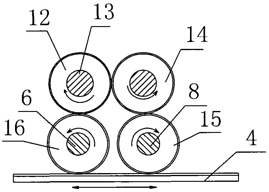
[0021] Example 1: In the design of the present invention, the number of each face tooth on the double-sided rack is greater than or equal to the number of the upper and lower transmission gears 5, 7. The double-sided rack 4 can drive the upper and lower transmission gears 5 and 7 at the same time. Rotate for two weeks.

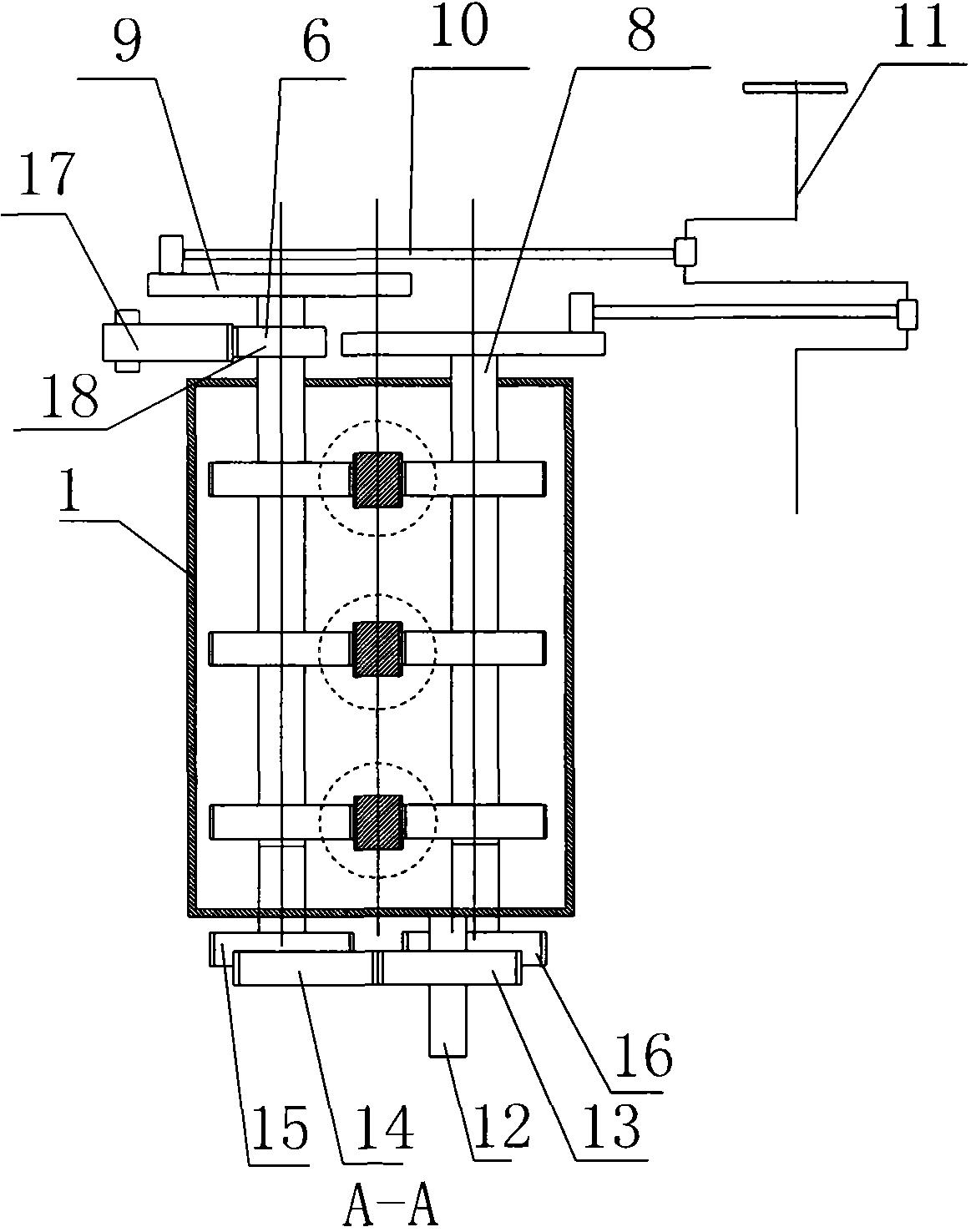
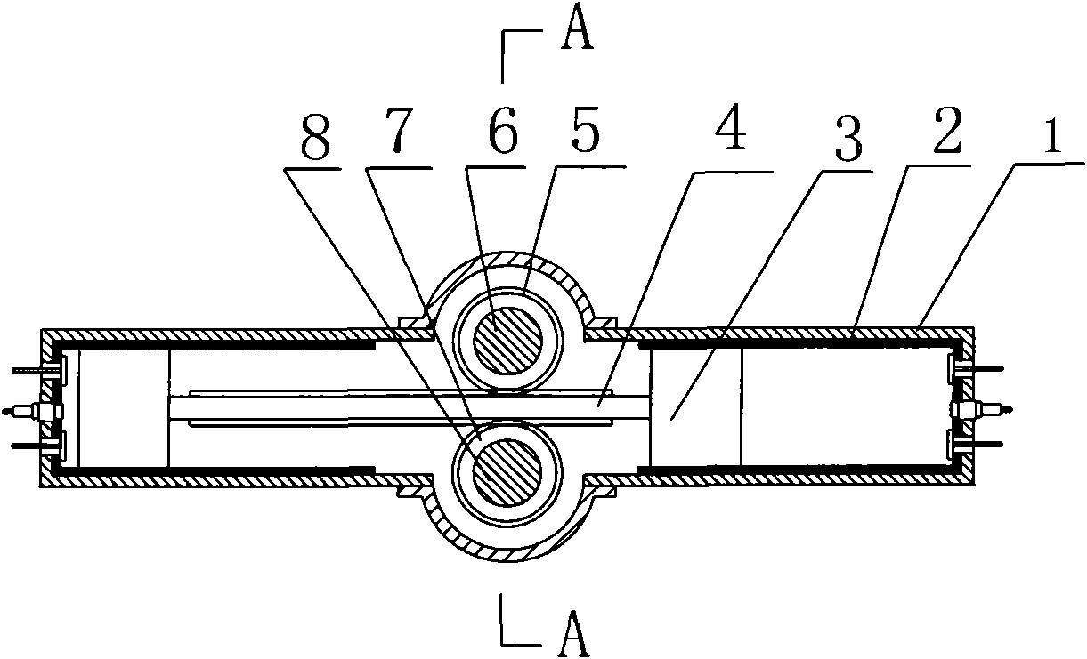
[0022] If a sector gear 17 with an arc length equivalent to the compression stroke of the piston is used to mesh with the start gear 18 provided on the upper transmission shaft 6 or the lower transmission shaft 8 for engine start, such as figure 2 As shown, the number of teeth of the double-sided rack 4 can be greater than the gears of the upper transmission gear 5 and the lower transmission gear 7, that is, the double-sided rack 4 can drive the upper and lower transmission gears 5 and 7 to rotate for more than two revolutions. The working frequency of the piston can be increased by at least more than one time, and the power can be increased by more than one time...

Embodiment 2

[0026] In calculating the compression ratio and ignition time, the double-sided rack-and-pinion direct drive structure of the present invention is also simpler and more convenient than the traditional crankshaft-connecting rod structure, because the stroke of the piston is the moving distance of the rack. Direct measurement of the forward and reverse rotation of the drive shaft enables people to select and measure the best ignition time or compression ratio to obtain the greatest fuel-saving effect and power output.

[0027] The engine cylinders are arranged in two rows opposite each other in the engine housing, and the middle is connected by a gear box. In this way, the processing is divided into three parts, and the process becomes quite simple, which provides convenience for assembly and maintenance.

[0028] The ignition system, the intake and exhaust system, the cooling system and the lubrication system of the engine of the present invention are the same as those of the traditi...


PUM


Abstract

The invention provides a piston-type direct-drive engine and a design method for first taking force and then integrating; symmetric pistons are arranged in an engine shell to directly drive a double-sided rack between the pistons to move back and forth; the double-sided rack drives two sets of gears to drive a transmission shaft to rotate back and forth to externally output two circuits of intermittent rotating force in opposite directions; and then a crankshaft connecting rod-type or a single gear-type power integrating mechanism integrates the two circuits of intermittent rotating force in opposite directions into continuous rotating force in a direction. The pistons are arranged in a cylinder tube and are connected with both ends of the double-sided rack; the upper side and the lower side of the double-sided rack are respectively provided with an upper transmission shaft and a lower transmission shaft; an upper transmission gear and a lower transmission gear are respectively arranged on the upper and the lower transmission shafts and are meshed with the upper sided rack and the lower sided rack of the double-side rack, and the upper and the lower transmission shafts are connected with the power integrating mechanism; the power integrating mechanism comprises an eccentric wheel, a connecting rod and a crankshaft; the eccentric wheel is connected with the ends of the upper and the lower transmission shafts; and both ends of the connecting rod are connected with the eccentric wheel and the crankshaft.

Description

Technical field [0001] The invention relates to a piston direct-drive engine, in particular to a piston-type direct-drive engine and an integrated design method after taking power first. Background technique [0002] Direct drive engines have been published in the patent literature, such as "new piston engine, patent number 01120523.7"; "one-stroke counter-explosion free piston engine, patent number 94238030.4" "variable output speed no connecting rod reciprocating piston engine, patent No. 200510096455.9". The technologies disclosed in the above documents are all opposed-piston direct-drive engines, and the core issues discussed are how to take power. For example, Patent No. 01120523.7" uses two one-way gears with ratchet teeth and a double-sided rack connecting the pistons. Engage to output force in one direction of rotation. The piston engine of "Patent No. 94238030.4" uses half gears to mesh with racks to take force; Patent No. 200510096455.9 uses planetary gears to take out...

Claims


Application Information

Patent Timeline
Patent Type & Authority Applications(China)
IPC IPC(8): F02B75/28
Inventor 姜明
Owner HAIMEN THE YELLOW SEA ENTREPRENEURSHIP PARK SERVICE CO LTD
Why Eureka
Try Eureka