
Fume impact water-spinning LNG heating and gasifying device

A gasification device, water-type technology, applied in fixed-capacity gas storage tanks, gas/liquid distribution and storage, non-pressure vessels, etc., can solve the problem of large daily gas supply, low gasification rate and thermal efficiency, complex structure, etc. problems, to achieve the effect of ensuring safe operation, increasing flue gas velocity, and increasing heat transfer effect

Inactive Publication Date: 2012-01-11
SHANGHAI UNIV OF ENG SCI
View PDF0 Cites 0 Cited by
  • Summary
  • Abstract
  • Description
  • Claims
  • Application Information

AI Technical Summary

Problems solved by technology

At present, in the communities of some large and medium cities, it is especially necessary to adapt to the small and medium-scale gas supply, that is, the gas supply per hour is about 5,000 to 10,000 cubic meters, and the structure is compact, the investment is low, the thermal efficiency is high, and the gas supply speed is fast. , suitable for peak-shaving heating and gasification devices. Looking at the above-mentioned prior art heating and gasification furnaces, they are not suitable, or the structure is too complicated, the investment is high, and the daily gas supply is too large or too small, which is not suitable for regional life supply. or the heating and gasification is unstable, the gasification rate and thermal efficiency are low, and cannot be adjusted automatically, and cannot meet the occasions with large differences between peaks and valleys. Therefore, changes and improvements are urgently needed

Method used


Image

  • Fume impact water-spinning LNG heating and gasifying device
  • Fume impact water-spinning LNG heating and gasifying device
  • Fume impact water-spinning LNG heating and gasifying device

Examples


Embodiment Construction

[0043] The structure of the present invention will be further described in detail below in conjunction with the accompanying drawings.

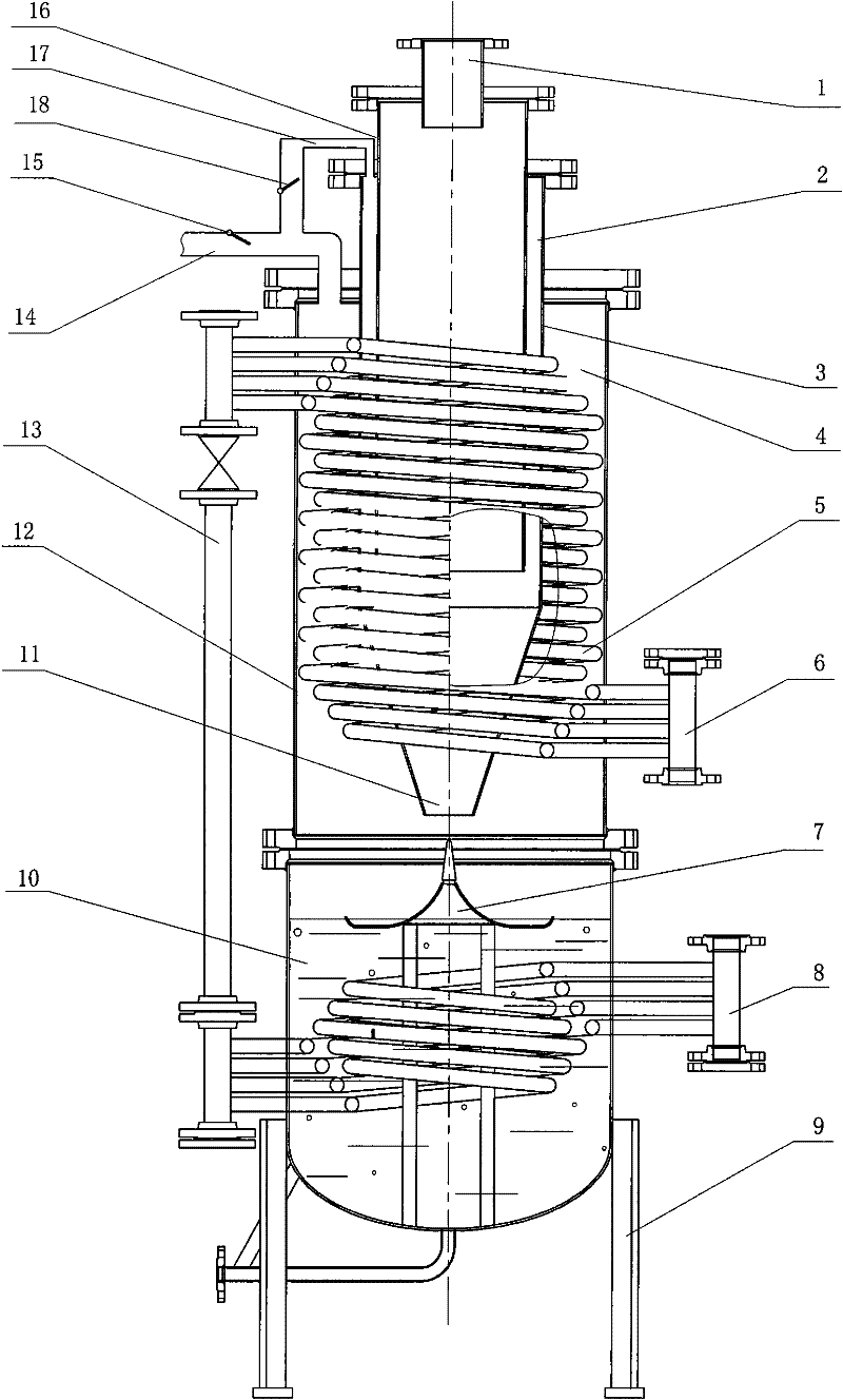
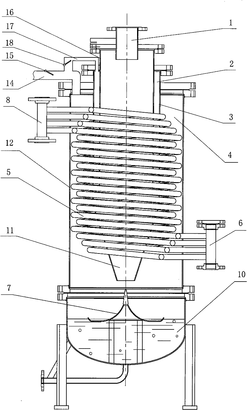
[0044] A flue gas impingement hydrocyclone type LNG heating gasification device, a combustion chamber is installed on the top of a vertical airtight cylindrical shell 12, the combustion chamber is composed of an inner cylinder 16 and an outer cylinder 3, and a burner 1 is installed on the top of the inner cylinder 16 , the lower end of the outer cylinder 3 is a conical spout 11; a heat exchange surface arrangement space 4 is formed between the outer wall of the outer cylinder 3 and the inner wall of the cylindrical shell 12, and a smoke exhaust pipe 14 is provided on the upper part of the heat exchange surface arrangement space 4; A jacket layer 2 is formed between the combustion outer cylinder 3 and the inner cylinder 16, the top of the jacket layer 2 communicates with the circulating flue 17, and the outlet at the bottom communicates with th...


PUM


Abstract

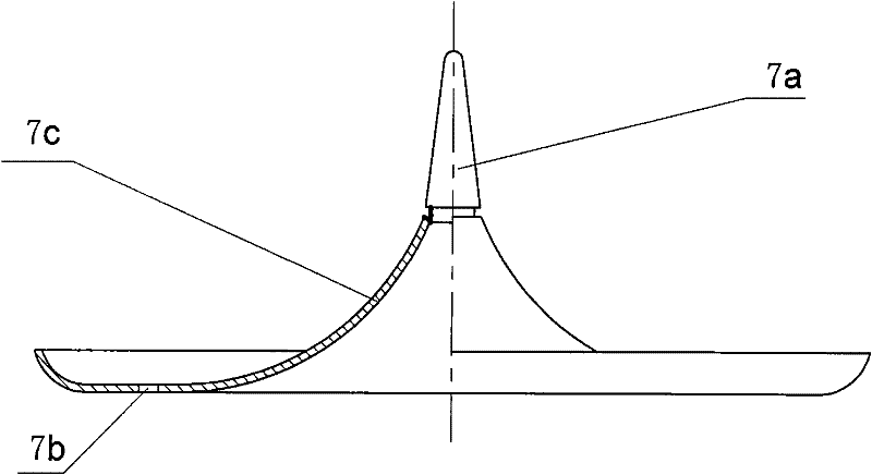
The invention relates to an LNG heating and gasifying device applicable to medium-scale and small-scale areas, in particular to a fume impact water-spinning LNG heating and gasifying device, wherein the top of a cylindrical shell (12) is provided with a combustion chamber which comprises an inner barrel (16) and an outer barrel (3), the top of the inner barrel (16) is provided with a combustor (1), the lower end of the outer barrel (3) is provided with a conical spout (11), a heat exchange surface arrangement space (4) is formed between the outer barrel (3) and the shell (12), a fume exhaust pipeline (14) is arranged at the upper part, a jacket layer (2) is formed between the outer barrel (3) of the combustion chamber and the inner barrel (16), the bottom of the jacket layer (2) is communicated with the conical sprout (11) and the top thereof is communicated with the fume exhaust pipeline (14) by a circulating flue (17), the lower part of the shell (12) is provided with a water pool (10) for storing water, an inverted umbrella-shaped pneumatic water spinner (7) is soaked in the water surface part of the water pool (10), and pile coils (5) which are arranged round the outer barrel (3) of the combustion chamber in a spiral ascending manner are arranged in the heat exchange surface arrangement space (4). The invention has simple and compact structure, wide work load range, convenient operation and maintenance, high heat efficiency and quick speed for gas supply, and is suitable for heating and gasifying LNG by medium-scale and small-scale gasification stations.

Description

technical field [0001] The invention relates to an LNG heating gasification device, in particular to an LNG heating gasification device suitable for use in small and medium-sized areas. Background technique [0002] Natural gas is a combustible gas that is naturally mined in the gas field. The main components are methane, ethane and other gases. At the time of consensus, natural gas is becoming more and more popular as a clean energy source, and many countries have listed it as the preferred fuel. The proportion of natural gas in energy supply has increased rapidly, so it has become one of the directions of world energy development. According to China's natural gas use plan, domestic production capacity will reach 90 billion cubic meters in 2010, and will reach 240 billion cubic meters by 2020. In terms of imported natural gas, the National Development and Reform Commission predicts that by 2020, China will import 35 billion cubic meters, equivalent to At 25 million tons / ye...

Claims


Application Information

Patent Timeline
Patent Type & Authority Patents(China)
IPC IPC(8): F17C7/04F17C9/02
Inventor 曹伟武严平钱尚源刘伟军
Owner SHANGHAI UNIV OF ENG SCI
Learn More