
Method and device for improving heat efficiency of combustion furnace by oxygen-rich partial oxygen-enriched jet flow combustion supporting

A technology of a fuel injection device and a combustion furnace, which is applied in the field of comprehensive energy saving and emission reduction, can solve the problems of reducing the air intake, limited temperature measurement points, unscientific and other problems, and achieves the effects of reducing the combustion air volume, increasing the temperature, and improving the heat radiation of the flue gas.

Inactive Publication Date: 2010-07-14
魏伯卿
View PDF15 Cites 18 Cited by
  • Summary
  • Abstract
  • Description
  • Claims
  • Application Information

AI Technical Summary

Problems solved by technology

[0003] 目前国内有沈光林等申请过局部增氧助燃的专利(CN97104465.1、CN00110217.6、CN02281418.3、CN200420004099.4、CN200420014005.1),另外沈博(CN101487593A)和魏伯卿(200920023792.9、200920195965.5、200920195812.0、 200920195966.X) also applied for the improved patents of local oxygen-increasing combustion-supporting energy-saving and its devices, but these patents only considered the problem from practical application, and did not solve the problem from the essence of improving thermal efficiency-improving heat radiation efficiency:
[0004] 1. These patents only focus on using the most advanced membrane oxygen production technology to obtain oxygen-enriched gas with a concentration of about 30%, replacing part of the combustion air to reduce the air intake, thereby reducing the heat taken away by the inert gas, and considering increasing the oxygen content to promote complete combustion So as to achieve energy saving; but there is no more consideration of how to make full use of these limited oxygen-rich resources to increase their thermal radiation efficiency
[0005] 2. Common oxygen nozzles are used without debugging devices, and the position and angle of oxygen nozzles are the most critical factors for local oxygen-increasing combustion and energy-saving efficiency. Therefore, it is impossible to adjust the oxygen-enriched nozzles without adjustable debugging devices. optimal position and angle
[0006] 3. The position, angle and linear velocity of the oxygen-enriched gas entering the combustion flame area are wrong: at present, the oxygen-enriched gas is sent to the center of the combustion flame, and the angle between the oxygen-enriched gas and the fuel nozzle is only a few degrees, and the linear velocity of the oxygen-enriched gas is relatively It is impossible to send the oxygen-enriched gas into the most critical area of ​​the combustion flame, so it is impossible to shorten the length of the combustion flame and prolong the residence time of the combustion flue gas in the furnace, let alone maximize Maximize the temperature in a certain area of ​​the flame, thereby maximizing the efficiency of heat radiation
[0007] 4. It is unscientific to debug completely by experience: Although there is no calculation method to calculate the optimal position and angle of oxygen-enriched nozzle design, combustion is a very complicated chemical process, and any combustion furnace with its original temperature measurement The points are very limited, and have nothing to do with the furnace heat radiation and its distribution, so it is unscientific to set the position and angle of the nozzle completely by experience

Method used


Image

  • Method and device for improving heat efficiency of combustion furnace by oxygen-rich partial oxygen-enriched jet flow combustion supporting
  • Method and device for improving heat efficiency of combustion furnace by oxygen-rich partial oxygen-enriched jet flow combustion supporting
  • Method and device for improving heat efficiency of combustion furnace by oxygen-rich partial oxygen-enriched jet flow combustion supporting

Examples


Embodiment Construction

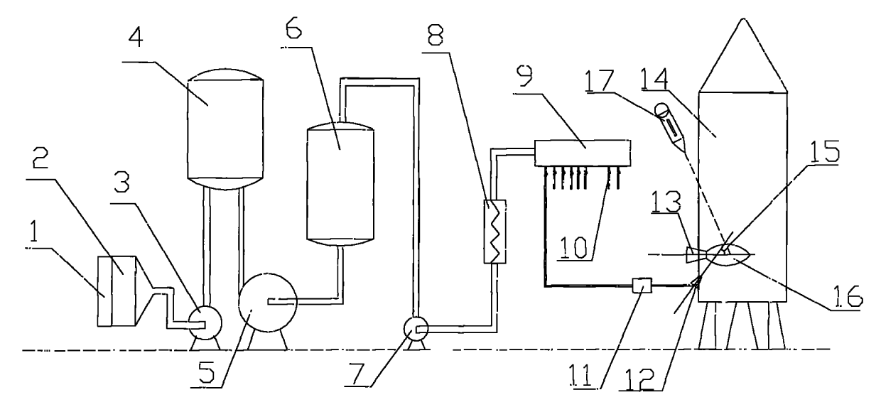
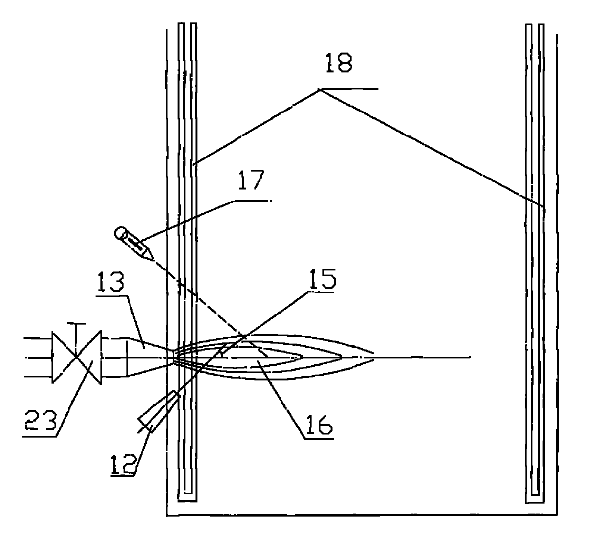
[0030] exist Figure 1-3In the shown embodiment: the filter cotton 1 is fixed on the inlet of the high efficiency air filter 2, the air supply device 3 is connected between the outlet of the high efficiency air filter 2 and the oxygen-enriched membrane device 4, and the outlet of the oxygen-enriched membrane device 4 is sequentially Connect the gas booster 7 through the vacuum pump 5 and the gas-water separation device 6, the gas booster 7 is a booster pump, the outlet of the gas booster 7 is connected to the inlet of the oxygen-enriched preheater 8, and the outlet of the oxygen-enriched preheater 8 The outlet is connected to the oxygen-enriched gas distributor 9, and each outlet pipeline of the oxygen-enriched gas distributor 9 is equipped with a regulating valve 10, and each regulating valve 10 is connected to a nozzle fine-tuning device 11 and a corresponding oxygen-enriched nozzle 12, a combustion furnace 14 Two oxygen-enriched nozzles 12 are arranged symmetrically on both...


PUM


Abstract

The invention discloses a method for improving the heat efficiency of a combustion furnace by oxygen-rich partial oxygen-enriched jet flow combustion supporting, which comprises the following steps of: introducing a fuel and an oxygen-rich gas into the combustion furnace respectively; and gathering the fuel and the oxygen-rich gas together for combustion, wherein the oxygen-rich gas is pressurized first, then is jetted into a fuel flow area at a linear velocity which is 1.2 to 4.0 times the flow velocity of the fuel by forming an angle of 10 to 45 degrees with the jetted fuel, and is mixed with the fuel for combustion, and the entering position of the oxygen-rich gas is an area which is between the top end of a combustion flame and a jet tip and is 1 / 4 to 4 / 2 away from the jet tip of a fuel nozzle. The invention also provides a device for improving the heat efficiency of the combustion furnace by the oxygen-rich partial oxygen-enriched jet flow combustion supporting. The method and the device has the following advantages that: by using a special oxygen-rich jet flow nozzle and a heat radiation principle, not only the duel energy-saving efficiencies of reducing the combustion-supporting air volume and completely combusting the fuel are kept, but also the temperature of a combustion flame area can be raised to the utmost extent, so the flue gas heat radiation is improved to the utmost extent.

Description

technical field [0001] The invention relates to a method and a device for improving the thermal efficiency of a combustion furnace by enriching oxygen with local oxygen-increasing jets, which is suitable for various fuels and all kilns, such as industrial boilers, heating furnaces, smelting furnaces, ceramic kilns, and glass kilns with fuel and gas. , cement kilns, etc., which belong to the field of comprehensive energy-saving and emission-reduction technologies. Background technique [0002] At present, ordinary kilns use ordinary air to support combustion. Since the air only contains 20.93% oxygen, the rest is inert gas. These inert gases not only do not support combustion, but absorb a lot of heat, which greatly reduces the performance and efficiency of the kiln. [0003] 目前国内有沈光林等申请过局部增氧助燃的专利(CN97104465.1、CN00110217.6、CN02281418.3、CN200420004099.4、CN200420014005.1),另外沈博(CN101487593A)和魏伯卿(200920023792.9、200920195965.5、200920195812.0、 200920195966.X) also applied for the ...

Claims


Application Information

Patent Timeline
IPC IPC(8): F23L7/00
CPCY02E20/34
Inventor 魏伯卿
Owner 魏伯卿
Learn More