Low pressure molding package structure for fuel cell

A low-pressure molding, fuel cell technology, applied to fuel cell type half cells and primary cell type half cells, structural parts, battery pack parts, etc. problems such as the structural surface of the adhesive material to achieve the effect of simplifying the production process and eliminating air bubbles

Inactive Publication Date: 2010-07-21
HIGH TECH BATTERY INC
View PDF1 Cites 13 Cited by
  • Summary
  • Abstract
  • Description
  • Claims
  • Application Information

AI Technical Summary

Problems solved by technology

[0004] (1) Because the overall structure of the air electrode itself has a porous structure with fine holes, it contains a large amount of air, so that when the battery pack is set up, no matter whether alkali-resistant glue (epoxy) or hot-melt glue is used, it is often easy to produce air bubbles when the glue is formed. , and form a channel with the outside world, which will cause leakage
[0005] (2) The air electrode is a structure composed of carbon powder and binder (binder), such as polytetrafluoroethylene, so the mechanical strength of the electrode itself is low, and it is easily affected by external vibrations, resulting in changes in shape, thermal expansion and cold contraction and other effects, and then destroy the structural surface of the air electrode and the sealing material, and because of the different material properties of the two, it is easy to produce cracks at the junction of the air electrode and the sealing material, resulting in liquid leakage
In fact, the surface of the air electrode in contact with the separator is made of hydrophilic carbon material, which has the characteristics of absorbing electrolyte and forming electrolyte flow channels. Therefore, the traditional press-fit package cannot effectively block the electrolyte leakage
[0006] (3) Although the air electrode has a porous structure with fine holes, air can freely enter and exit to produce a reaction, but when there is zinc oxide deposited on the surface of the separator in the air electrode, the dense zinc oxide will form a resistance at this time. The broken area prevents the gas generated inside the battery from being discharged, resulting in excessive internal pressure, which in turn affects the bonding strength of the junction between the air electrode and the sealing material, resulting in liquid leakage
[0007] Although there were patents in the past, such as US Patent Publication No. 2008 / 0160413A1, the concept of encapsulation with hot-melt adhesive was proposed, but the encapsulation method was mainly based on adhesion or caulking to achieve the purpose of encapsulation, rather than truly and effectively achieving The real sealing and leak-proof effect needs to be improved urgently

Method used


Image

  • Low pressure molding package structure for fuel cell
  • Low pressure molding package structure for fuel cell
  • Low pressure molding package structure for fuel cell

Examples


Embodiment Construction

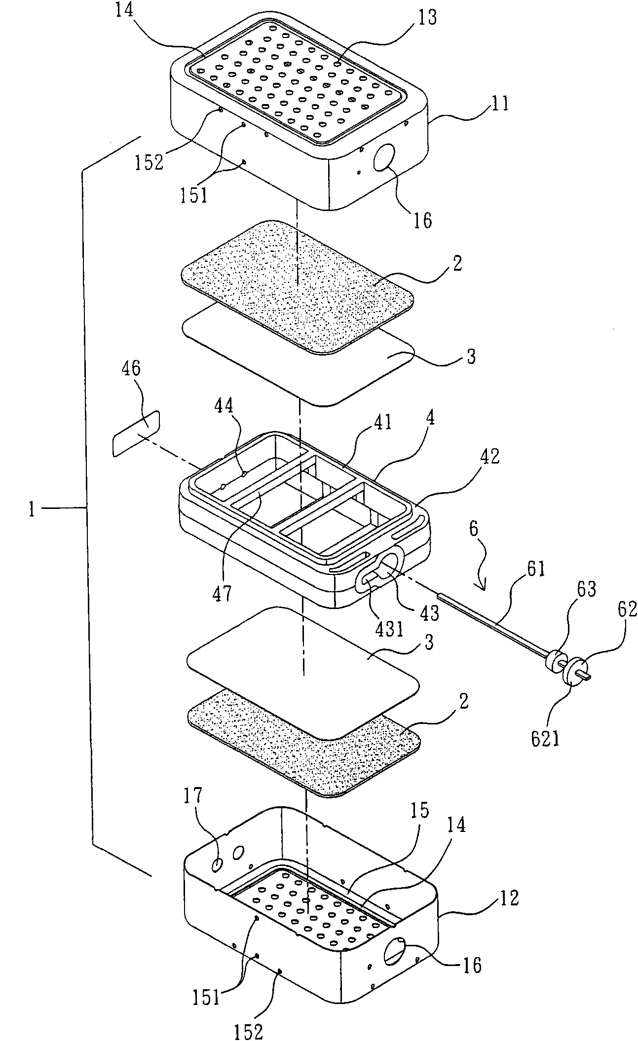
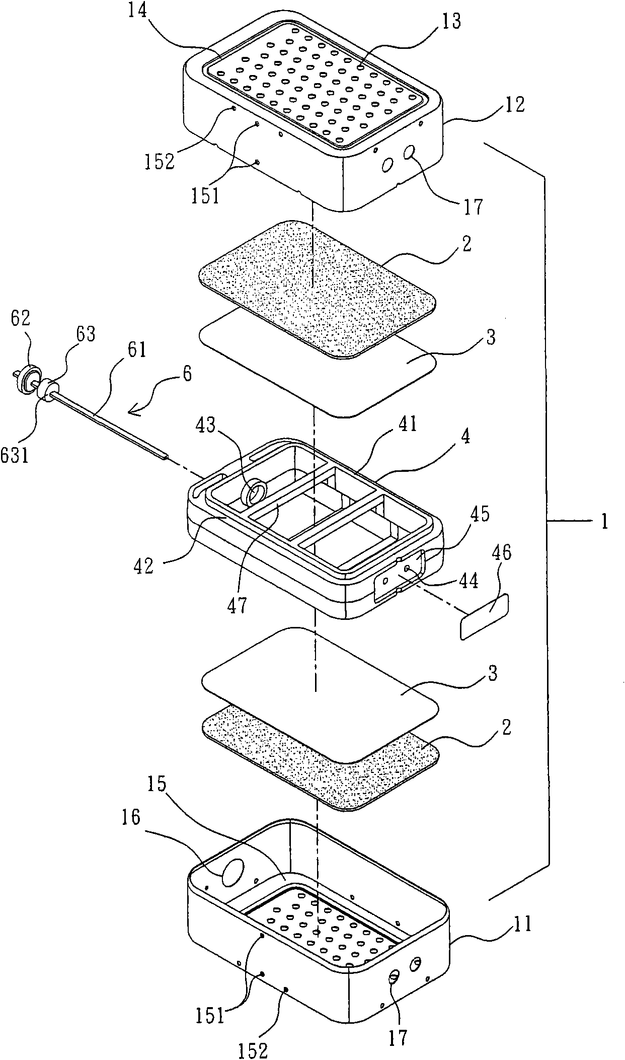
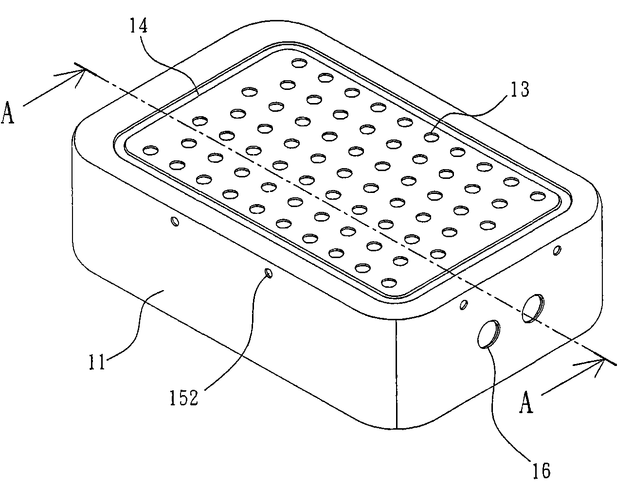
[0031] In order to further disclose the specific technical content of the present invention, first please refer to the accompanying drawings, wherein, figure 1 It is an exploded perspective view of the first embodiment of the fuel cell of the present invention; figure 2 for figure 1 An exploded perspective view of the shown fuel cell from another perspective; Figure 3a and Figure 3b It is a perspective view of different viewing angles after the first embodiment of the fuel cell of the present invention is assembled; Figure 4 for Figure 3a a sectional view taken along the line A-A; Figure 5 for Figure 3b a sectional view taken along the line B-B; Image 6 It is an exploded perspective view of the second embodiment of the fuel cell of the present invention; Figure 7 for Image 6 An exploded perspective view of the shown fuel cell from another perspective; Figure 8 It is an assembled perspective view of the second embodiment of the fuel cell of the present inven...


PUM

PropertyMeasurementUnit
tackinessaaaaaaaaaa
compressive strengthaaaaaaaaaa
ductilityaaaaaaaaaa

Abstract

The invention discloses a low pressure molding package structure for a fuel cell, which comprises a shell, an air electrode and a separation film, a hollow fixing piece, and a hot melt adhesive layer. A plurality of air holes are formed on at least one surface of the shell and the periphery of an inner surface of each air hole is provided with a recessed first accommodating part. The air electrode and the separation film are superposed on the inner surfaces of the plurality of air holes. The hollow fixing piece is arranged in the shell, the surface adjacent to the separation film is provided with an annular flange in a projection mode, and a recessed second accommodating part is formed outside the annular flange. The second accommodating part and the first accommodating part enclose to form a C-shaped flow channel. A hot melt adhesive in a melting state is injected from an injection orifice of the shell or the fixing piece in a low pressure molding mode, so that the hot melt adhesive flows in the C-shaped flow channel and closely adheres and coats the edges of the air electrode and the separation film; and when the hot melt adhesive is cooled and cured, a circle of hot melt adhesive layer which has elasticity and adhesiveness and tightly compresses the air electrode is formed so as to block the leakage of the liquid in the cell.

Description

technical field [0001] The invention relates to a fuel cell, in particular to a low-pressure molding packaging structure of the fuel cell to prevent electrolyte leakage inside the cell. Background technique [0002] Existing fuel cells, such as zinc-air batteries, are composed of a casing, a zinc-air battery module, and a power transmission interface. The zinc-air battery produces an electrochemical oxidation-reduction reaction (main reaction) through zinc powder and oxygen in the air, and then generates electricity; hydroxide ions (OH) in the reaction - ), must pass through the alkaline electrolyte contained in the battery, such as potassium hydroxide aqueous solution as a medium, and be transported from the air cathode to the zinc anode in order to carry out the full battery reaction. The zinc anode of the zinc-air battery is mainly composed of zinc metal powder gel, zinc metal sheet, or zinc metal powder pressed plate, but when zinc comes into contact with the alkaline e...

Claims


Application Information

Patent Timeline
Patent Type & Authority Applications(China)
IPC IPC(8): H01M12/06H01M2/08
CPCY02E60/128Y02E60/10
Inventor 王贵云
Owner HIGH TECH BATTERY INC
Why Eureka
Try Eureka