High pressure powder-spray nozzle for high pressure powder spray method

A high-pressure jet and powder technology, which is applied in the fields of soil protection, construction, and infrastructure engineering, can solve the problems of insufficient foundation reinforcement, affecting water-stopping effect, and low cement-soil strength, achieving good water-stopping effect, The effect of increasing the reinforcement range and reducing the water content

Inactive Publication Date: 2010-07-28
CENT RES INST OF BUILDING & CONSTR CO LTD MCC GRP +1
View PDF5 Cites 8 Cited by
  • Summary
  • Abstract
  • Description
  • Claims
  • Application Information

AI Technical Summary

Problems solved by technology

Due to the limitation of the high-pressure delivery pump, the water-cement ratio of the high-pressure cement slurry jet is usually ≥1.0. Compared with the water-cement ratio of 0.4-0.5 in the deep mixing method, the water content of the cement-soil admixture formed by the jet grouting method is large, and the same cement content On the other hand, since a large amount of water (water in high-pressure water jet and high-pressure cement slurry jet) is injected into the soil during jet grouting reinforcement, especially for jet grouting The grout method is widely used in the water-stop reinforcement project of saturated sand layer. Since the cement-soil (mortar) water-cement ratio formed by jet grouting is large, usually ≥ 2.0, the cement-soil (mortar) segregates during the consolidation process, forming vertical irregularities. The continuous "cake-like" reinforcement seriously affects the water-stop effect; at the same time, the strength in a certain range at the bottom of the reinforcement is very low or even has no strength, which fails to achieve the purpose of foundation reinforcement

Method used


Image

  • High pressure powder-spray nozzle for high pressure powder spray method
  • High pressure powder-spray nozzle for high pressure powder spray method
  • High pressure powder-spray nozzle for high pressure powder spray method

Examples


Embodiment Construction

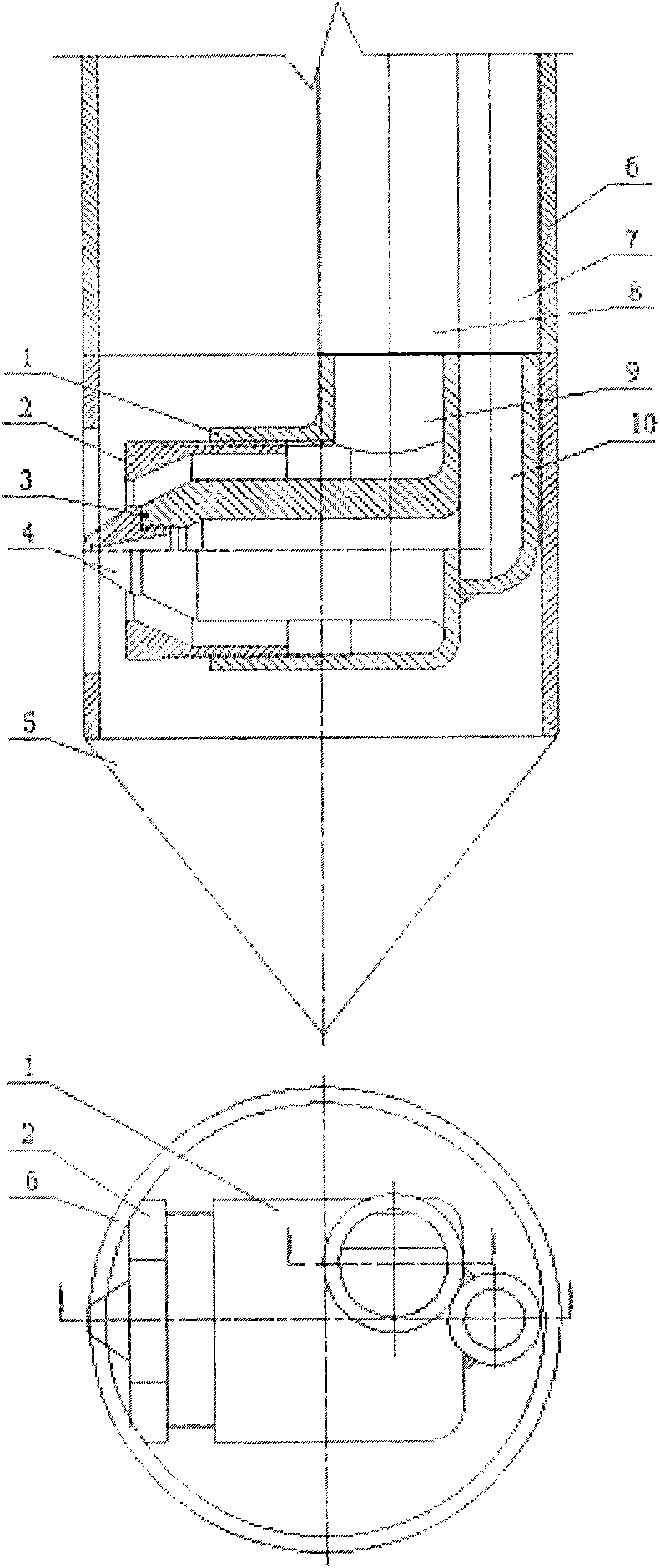
[0026] Such as figure 1 as shown, figure 1 It is a structural schematic diagram of the high-pressure jet powder nozzle of the present invention.

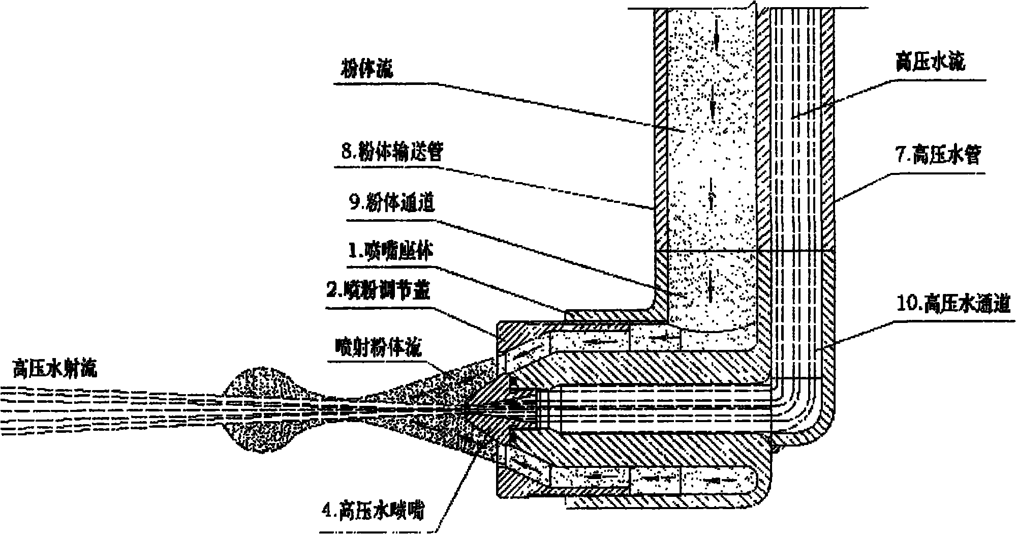
[0027] The high-pressure jet powder nozzle includes: nozzle base 1, powder spraying adjustment cover 2, sealing ring 3, high-pressure water nozzle 4, drill bit 5, drill pipe 6, high-pressure water pipe 7, powder conveying pipe 8, powder channel 9 and The high-pressure water channel 10 is characterized in that: the high-pressure jet powder nozzle is installed inside the drill bit 5, the drill bit 5 is connected to the drill pipe 6, and the high-pressure water nozzle 4 and the high-pressure water channel 10 of the nozzle base 1 are connected by threads , the powder spraying regulating cover 2 is threadedly connected with the powder channel 9 of the nozzle base 1, and is combined with the high-pressure water nozzle 4 to form an annular powder spraying nozzle, and the annular gap of the powder spraying nozzle is adjusted by rotating ...


PUM


Abstract

The invention relates to a high pressure powder-spray nozzle for a high pressure powder spray method, and aims to form a continuous and complete reinforced body with good water stop effect and expand the application range of a spraying and casting method in a underground water prevention and treatment project of a water-saturated sand layer, at the same time reduce the moisture content of the reinforced body, and contamination of mud and cement waste of a grout oozing body caused by the unit reinforced body, thereby reducing the construction costs. The nozzle comprises a nozzle base body, a powder spraying regulation cover, a sealing ring, a high-pressure water nozzle, a drill, a drill rod, a high-pressure water pipe, a powder conveying pipe, a powder passage and a high-pressure water passage, wherein the nozzle base body is connected with the drill rod; the drill rod is internally provided with the high-pressure water pipe and the powder conveying pipe; the high-pressure water nozzle is in thread connection with the high-pressure water pipe; the powder spraying regulation cover is in thread connection with the powder spraying passage; the powder spraying nozzle encloses around the high-pressure water nozzle, and has a certain conical degree; and when the powder is sprayed out, and ring form powder concentrates into a beam and spray to the high-pressure water jet.

Description

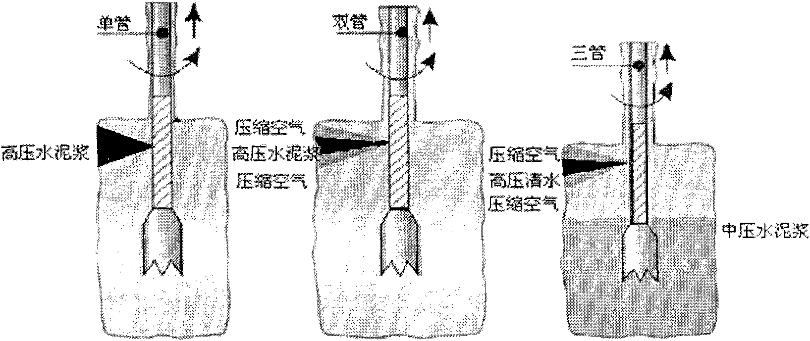
technical field [0001] The invention relates to a high-pressure powder injection nozzle used in a high-pressure powder injection method. Background technique [0002] Such as image 3 As shown at present, the basic types of jet grouting methods are single-pipe method, double-pipe method, and three-pipe method, and the basic reinforcement principles are as follows: [0003] Single-pipe method: the high-pressure cement slurry jet cuts the soil and mixes with the cut and broken soil; [0004] Double-pipe method: the annular compressed air and the high-pressure cement slurry jet are coaxial (air slurry coaxial) to spray the cut soil and mix with the cut and broken soil; [0005] Three-pipe method: annular compressed air and high-pressure water jet coaxial (air-water coaxial) spray cutting soil, and at the same time deliver medium and low-pressure cement slurry to the soil to mix with the cut and broken soil; [0006] It can be seen from the reinforcement principles of the thre...

Claims


Application Information

Patent Timeline
Patent Type & Authority Applications(China)
IPC IPC(8): E02D3/12
Inventor 王宪章吴旭君杨志银郑平张俊赵伟骆永生
Owner CENT RES INST OF BUILDING & CONSTR CO LTD MCC GRP
Why Eureka
Try Eureka