Full-gloss logic XNOR gate structure based on micro-ring resonator structure

A technology of micro-ring resonator and micro-ring resonator is applied in the field of all-optical logic XOR gate structure, which can solve problems such as extinction and achieve the effect of reducing working optical power

Inactive Publication Date: 2012-03-07
INST OF SEMICONDUCTORS - CHINESE ACAD OF SCI
View PDF0 Cites 0 Cited by
  • Summary
  • Abstract
  • Description
  • Claims
  • Application Information

AI Technical Summary

Problems solved by technology

At this time, the light wave is hardly detected at the output end of the nanowire waveguide, that is, the phenomenon of extinction occurs.

Method used


Image

  • Full-gloss logic XNOR gate structure based on micro-ring resonator structure
  • Full-gloss logic XNOR gate structure based on micro-ring resonator structure
  • Full-gloss logic XNOR gate structure based on micro-ring resonator structure

Examples


Embodiment Construction

[0033] In order to make the purpose, technical solution and advantages of the present invention clearer, the present invention will be further described in detail by taking the all-optical logic XNOR gate with SOI-based ridge microring resonator structure as an example and referring to the accompanying drawings.

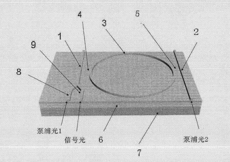
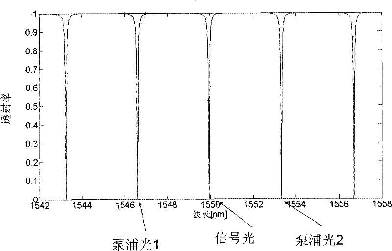
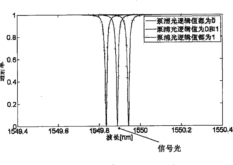
[0034] Such as figure 1 as shown, figure 1A schematic diagram of an all-optical logic XNOR gate structure based on a microring resonator structure provided by the present invention is shown, the structure includes a first nanowire waveguide 1, a second nanowire waveguide 2 and a microring resonator cavity 3, wherein the first A nanowire waveguide 1 and a second nanowire waveguide 2 are parallel to each other, the microring resonator 3 is located between the first nanowire waveguide 1 and the second nanowire waveguide 2, and the microring resonator 3 and the first nanowire waveguide 1 There is a certain gap between them and between the microring resonator 3 and the s...


PUM


Abstract

The invention relates to a full-gloss logic XNOR gate structure based on a micro-ring resonator structure, comprising a first nanowire waveguide, a second nanowire waveguide and a micro-ring resonant cavity, wherein the first nanowire waveguide and the second nanowire waveguide are parallel to each other, the micro-ring resonant cavity is positioned between the first nanowire waveguide and the second nanowire waveguide, gaps are respectively arranged between the micro-ring resonant cavity and the first nanowire waveguide and between the micro-ring resonant cavity and the second nanowire waveguide and ensure that the micro-ring resonant cavity satisfies critical coupling conditions so that light waves satisfying the resonant wavelength of the micro-ring resonant cavity can be completely coupled in the micro-ring resonant cavity through the first nanowire waveguide or the second nanowire waveguide, and the light extinction is realized on the output end of the first nanowire waveguide orthe second nanowire waveguide. The invention utilizes the two-photon absorption effect in the micro-ring resonant cavity to realize the logic function of full-gloss 'XNOR'.

Description

technical field [0001] The invention relates to the technical field of photonic devices, in particular to an all-optical logic XNOR gate structure based on a microring resonator structure. Background technique [0002] The all-optical logic gate is the basic logic unit and the key core device in future optical computing. Similar to logic gates in electronics, all-optical logic gates use photons in waveguides as information carriers, and modulate the output of signal light by controlling pump light. The corresponding relationship between the input and output terminals of the waveguide can constitute a truth table, in which the logic state ("0" or "1") is determined by the optical power of the pump light and signal light at the port: high power corresponds to the logic value "1", And low power corresponds to a logic value "0". The following truth table of "XOR" logic is shown in the following truth table: when the control signals A and B are both "1", the corresponding signa...

Claims


Application Information

Patent Timeline
Patent Type & Authority Patents(China)
IPC IPC(8): G02F3/00G02F1/365
Inventor 翟耀陈少武
Owner INST OF SEMICONDUCTORS - CHINESE ACAD OF SCI
Why Eureka
Try Eureka