Heat-gaining combined heat and power system

A heat-electricity-cooling combined supply and heat-increasing technology is applied in the application field of energy technology, which can solve the problems of not fully utilizing the heat of flue gas in the high-temperature section to work, and achieve the effects of improving efficiency, reducing exhaust gas temperature, and reducing emissions.

Active Publication Date: 2010-08-11
TSINGHUA UNIV +1
View PDF8 Cites 35 Cited by
  • Summary
  • Abstract
  • Description
  • Claims
  • Application Information

AI Technical Summary

Problems solved by technology

In addition, even if the absorption heat pump is used in winter and the heat of the flue gas in the high temperature section is used as the driving heat source to recover and utilize the waste heat

Method used


Image

  • Heat-gaining combined heat and power system
  • Heat-gaining combined heat and power system
  • Heat-gaining combined heat and power system

Examples


Embodiment 1

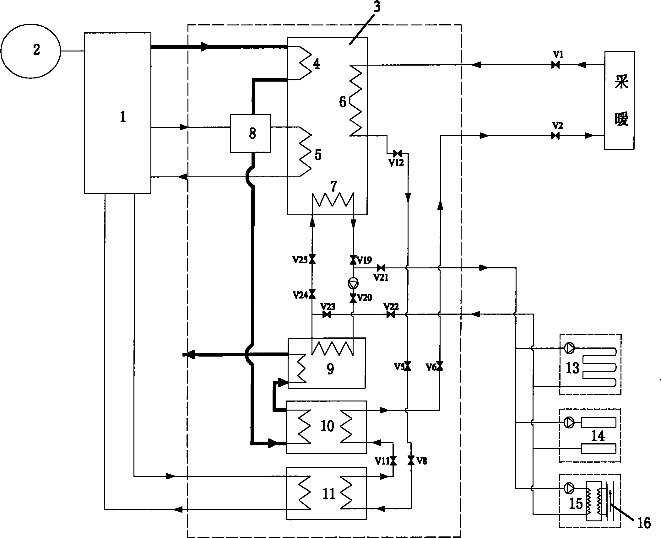
[0022] Example 1 as figure 2 As shown, the type of gas engine 1 is a gas internal combustion engine, and the high-temperature flue gas at 500 °C first enters the first generator 4 of the absorption heat pump 3 as a driving heat source and cools down to 170 °C to be discharged, and then enters the high-temperature flue gas-water heat exchanger 8 releases heat and cools down to 120°C, then enters medium-temperature flue gas-water heat exchanger 10 releases heat and cools to 60°C, and finally enters low-temperature flue gas-water heat exchanger 9 releases heat and cools to 25°C, and discharges to the atmosphere. After the high-temperature jacket water enters the high-temperature flue gas-water heat exchanger 8 to exchange heat with the flue gas, it enters the second generator 5 of the absorption heat pump 3 and then flows back to the gas internal combustion engine. The low-temperature intercooled water enters the water-water heat exchanger 11 and then flows back to the gas inter...

Embodiment 2

[0024] Example 2 as image 3 As shown, the type of gas engine 1 is a gas internal combustion engine, and the processes of flue gas, high-temperature jacket water, and low-temperature intercooling water are the same as in embodiment 1.

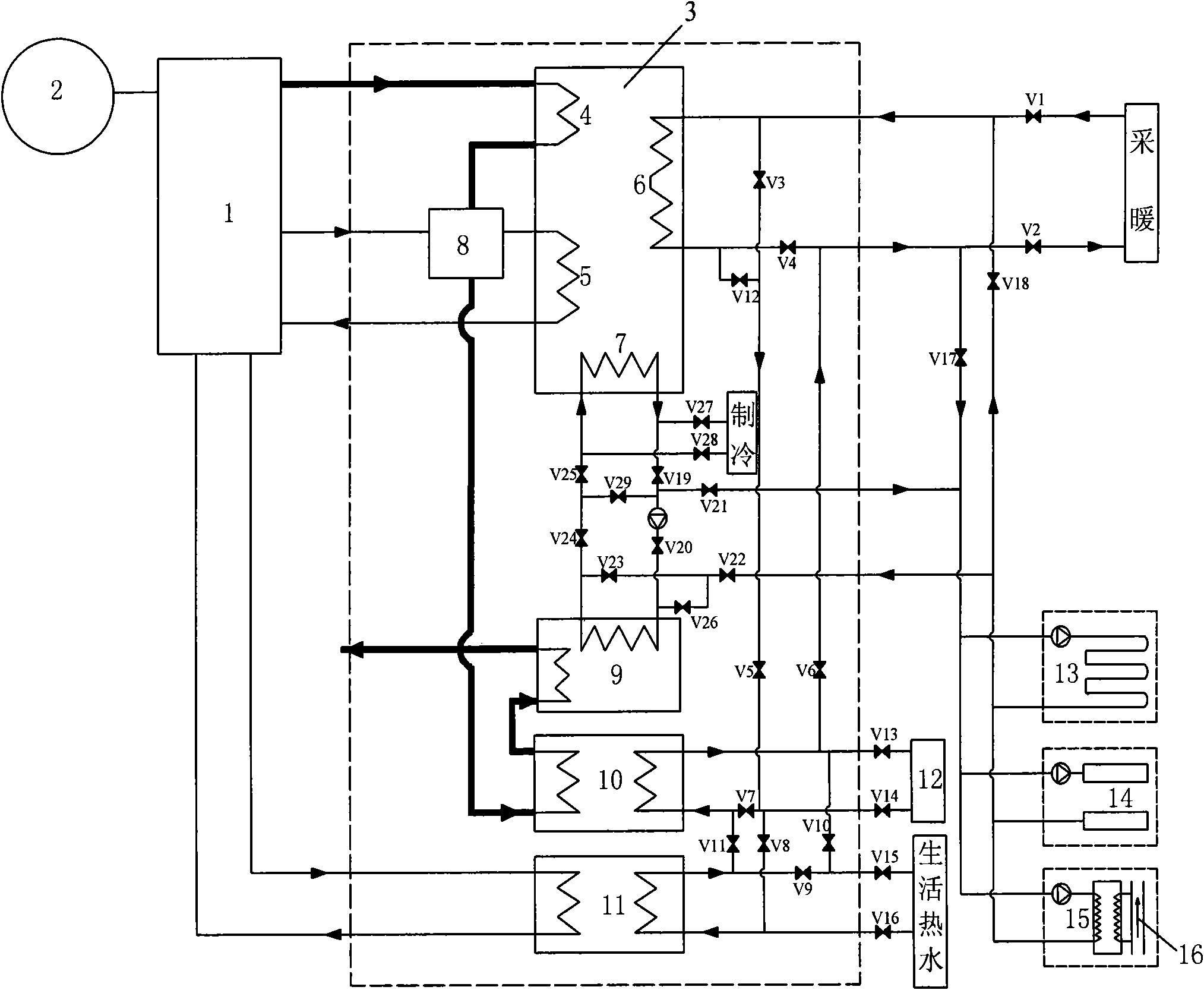
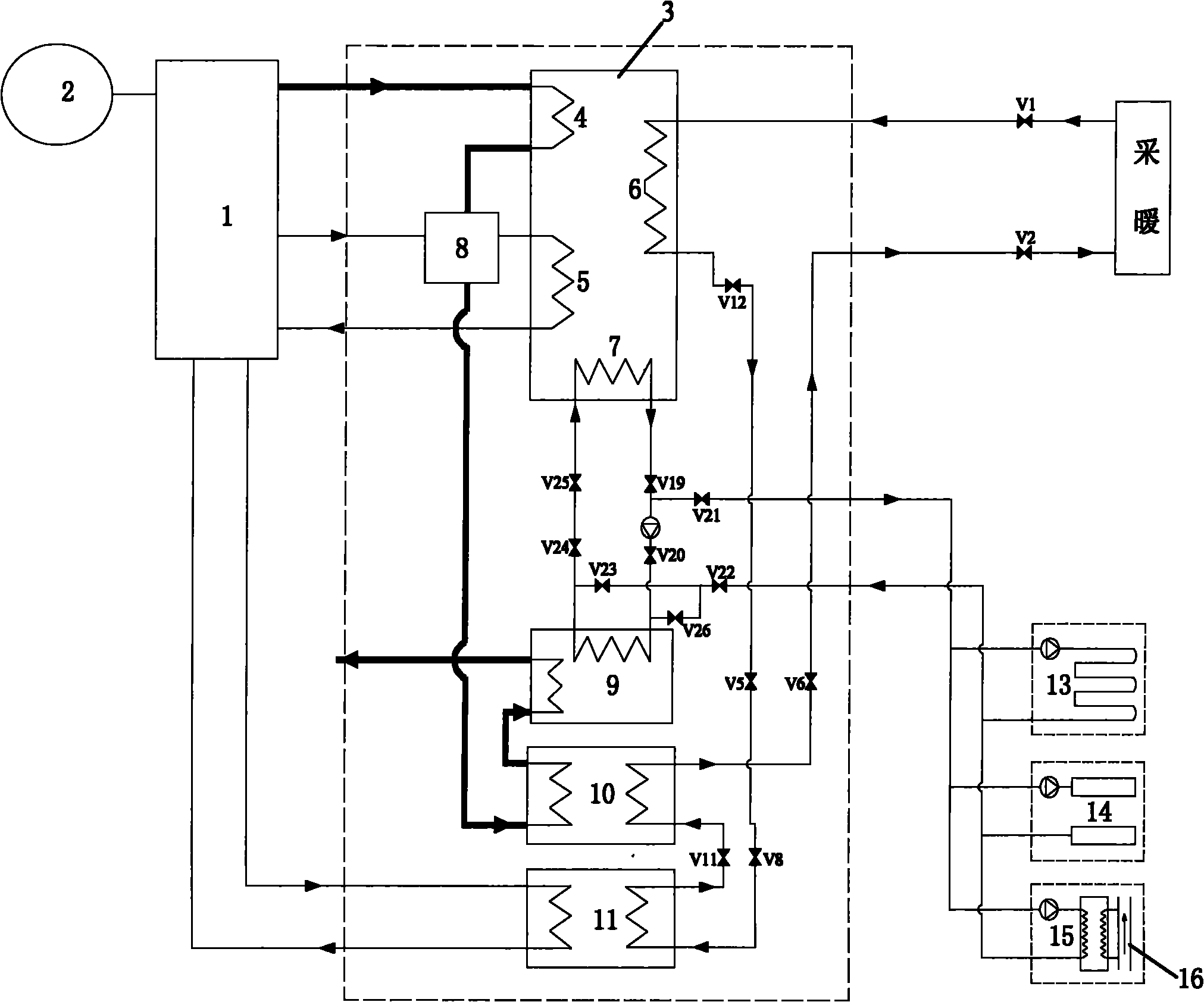
[0025] Embodiment 2 On the basis of Embodiment 1, a pipeline from the buried pipe 13 or the shallow groundwater well 14 or the sewage heat exchanger 15 to the water inlet of the low-temperature flue gas-water heat exchanger 9 and the pipeline located in the pipe are added. The valve on the road is the twenty-sixth valve V26. Under this heating condition, the first valve V1, the second valve V2, the fifth valve V5, the sixth valve V6, the eighth valve V8, the eleventh valve V11, the Twelfth valve V12, nineteenth valve V19, twenty-first valve V21, twenty-second valve V22, twenty-fourth valve V24, twenty-fifth valve V25, twenty-sixth valve V26 open, and other valves closed , the heating return water enters the condensation and absorber 6 of the a...

Embodiment 3

[0027] Example 3 as Figure 4 As shown, the type of gas engine 1 is a gas internal combustion engine, and the processes of flue gas, high-temperature jacket water, and low-temperature intercooled water are the same as those in Embodiment 1. Embodiment 3 On the basis of Embodiment 1, a pipeline from the heating return water to the water outlet of the condensation and absorber 6 of the absorption heat pump 3 and a third valve V3 located on the pipeline are added, and a pipeline from the water outlet of the condensation and absorber 6 to the water outlet of the absorption heat pump 3 is added. For the heating water supply pipeline and the fourth valve V4 on the pipeline, a pipeline from the heating return water to the water inlet of the medium-temperature flue gas-water heat exchanger 10 and the seventh valve V7 on the pipeline are added. - The pipeline from the water outlet at the low temperature side of the water heat exchanger 11 to the heating water inlet, and the ninth valve...


PUM


Abstract

The invention relates to a heat-gaining combined heat and power system, which belongs to the application field of the energy technology, and consists of a gas engine, a power generator, an absorption-type heat pump, a high-temperature smoke-water heat exchanger, a middle-temperature smoke-water heat exchanger, a low-temperature smoke-water heat exchanger, a water-water heat exchanger, a solution dehumidifying system, a ground heat exchanger, a superficial-layer underground water well or a sewage heat exchanger and accessories such as connection pipes and valves. The system can realize two work conditions of heat supply and coldness supply, and is provided with multiple pipeline switching forms under the work conditions of the heat supply and the coldness supply so as to adapt to the requirements of different situations; the system can ensure the adequate utilization of the heat of the gas engine, can adequately recycle the surplus heat of the exhausted smoke of the gas engine in winter, and can realize the extraction of the heat of the low-temperature heat source so as to improve the comprehensive efficiency of the system and to reduce the environmental pollution; and the system can discharge the heat of the low-temperate smoke and the heat of the cooling water into the low-temperature heat source to be stored in summer; and moreover combined with the solution dehumidification and the living hot water, the energy utilization efficiency of the system can be improved.

Description

technical field [0001] The invention belongs to the application field of energy technology, and relates to the structural improvement of a combined heating, power and cooling system, in particular to a heat-increasing type combined heating, power and cooling system. Background technique [0002] The gas-fired combined heating, power and cooling energy system has been increasingly valued worldwide due to its advantages of high efficiency, economy, and environmental protection. The current gas-fired cogeneration system generally uses high-temperature smoke exhaust to drive the absorption unit. In summer, the absorption refrigeration is used only as a heat exchanger in winter, and this part of the heat is directly used for heating. High energy and low use, the exhaust temperature is 100 Above ℃, the discharged medium-temperature flue gas not only has sensible heat, but also has a large amount of latent heat of vaporization that has not been utilized. Taking natural gas as an ex...

Claims


Application Information

Patent Timeline
IPC IPC(8): F25B29/00F25B27/02
CPCY02A30/274
Inventor 付林赵玺灵张世钢李锋朱建章江亿
Owner TSINGHUA UNIV
Why Eureka
Try Eureka