Manufacturing method of heat pipe

A manufacturing method and heat pipe technology, applied in the field of heat pipe manufacturing, can solve the problem that the heat pipe cannot adapt to efficient heat dissipation work, etc., and achieve the effects of improving heat conduction efficiency, small flow resistance, and increasing heat transfer.

Inactive Publication Date: 2010-08-11
ZHONGSHAN WEIQIANG TECH
View PDF0 Cites 13 Cited by
  • Summary
  • Abstract
  • Description
  • Claims
  • Application Information

AI Technical Summary

Problems solved by technology

[0003] With the miniaturization, high-speed, and high-efficiency of electronic products, the heat dissipation requirements are getting higher and higher. At present, the traditional heat pipes are gradually unable to adapt to efficient heat dissipation. Therefore, a heat pipe with higher thermal efficiency is required to meet the heat dissipation of the product. Require

Method used


Image

  • Manufacturing method of heat pipe
  • Manufacturing method of heat pipe
  • Manufacturing method of heat pipe

Examples


Embodiment Construction

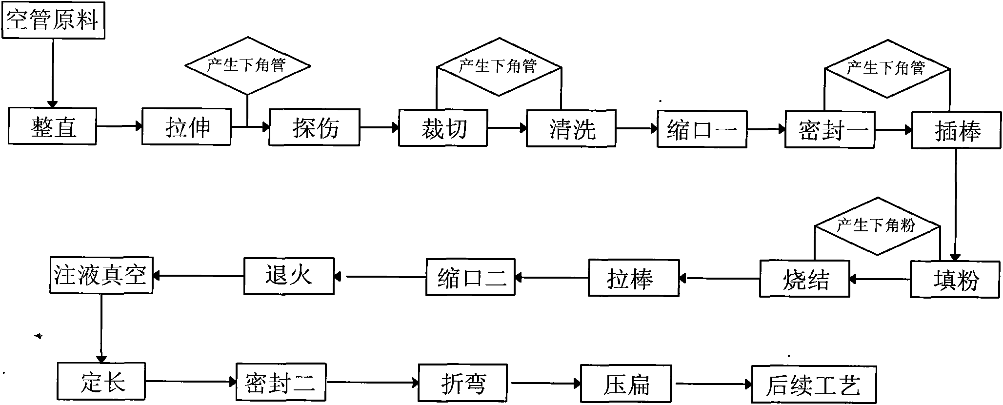
[0032] refer to figure 1 , a method for manufacturing a heat pipe provided by the present invention mainly consists of the following process steps:

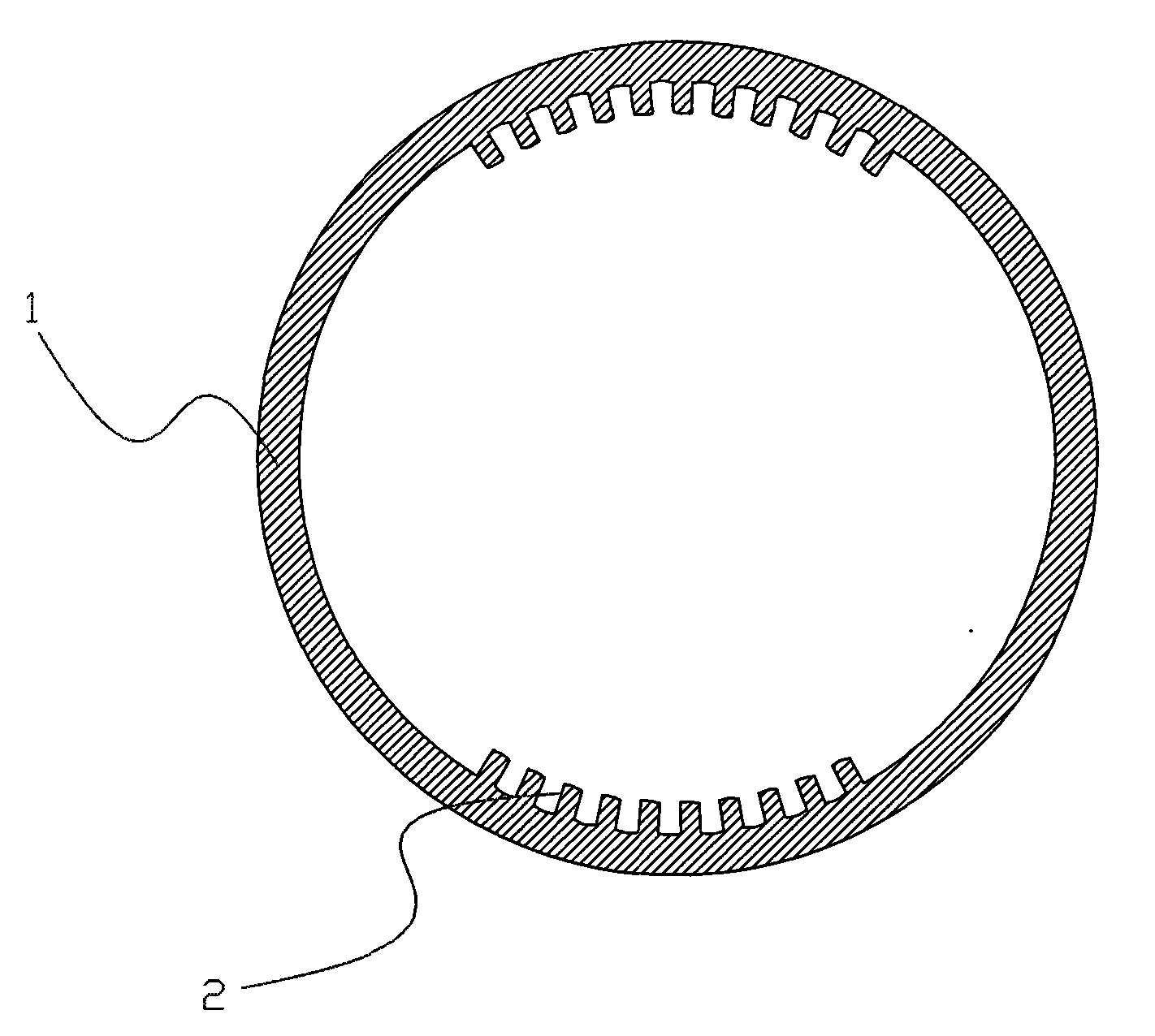
[0033] Step 1, prepare the raw material: prepare a kind of hollow tube raw material with two sets of symmetrical grooves along the axial direction of the inner wall, its structure is as follows figure 2 As shown, on the inner wall of the metal pipe body 1, there are two sets of grooves 2 at symmetrical positions, so that between the two grooves 2 is the smooth inner wall of the metal pipe body 1, and the grooves 2 are along the longitudinal direction of the pipe body 1. It is set and opened longitudinally on the pipe body 1, and its function is to circulate steam;

[0034] Step 2, cutting the empty pipe: cutting the empty pipe to a predetermined length;

[0035] Step 3, necking and sealing 1: shrinking the first end of the cut empty pipe and sealing the necking, preferably, the sealing method is spot welding;

[0036] Step 4,...


PUM


Abstract

The invention discloses a manufacturing method of a heat pipe, comprising the following steps: preparing raw materials, cutting a blank pipe, necking down and sealing A, filling in powder, sintering, necking down, sealing B and flooding in vacuum. The heat pipe manufactured with the technical method of the invention is provided with a groove part on the inner wall to ensure that the groove part is favorable for steam to flow to a condensing zone from the heat zone of the heat pipe, thus improving heat conduction efficiency; the inner side of the groove part is provided with a powder sintering part, and powder is bigger than a groove gap so as to avoid adverse effect caused by the way that power is clamped into the groove; a capillary gap between powder sintering parts can store more moisture so as to amplify heat transfer amount, and the flow resistance of condensation hydraulic fluid in the capillary gap becomes small so as to assist in improving the heat-conducting property of the heat pipe.

Description

technical field [0001] The invention relates to a heat pipe technology, in particular to a heat pipe manufacturing method. Background technique [0002] The heat pipe is a highly efficient heat transfer component, which is widely used in various industrial fields. It is mainly made by sealing the two ends of the metal pipe, injecting an appropriate amount of working fluid into the pipe, and vacuumizing it. When the heat source heats one end of the heat pipe, the working fluid absorbs heat and vaporizes. Under the action of pressure difference, the steam flows to the other end at high speed and releases latent heat to the cold source to condense. The heat source circulates in this way, and the heat is efficiently and quickly transferred from the heat source to the cold source. [0003] With the miniaturization, high-speed, and high-efficiency of electronic products, the heat dissipation requirements are getting higher and higher. At present, the traditional heat pipe is grad...

Claims


Application Information

Patent Timeline
Patent Type & Authority Applications(China)
IPC IPC(8): F28D15/02
Inventor 李克勤钟蜀龙
Owner ZHONGSHAN WEIQIANG TECH
Why Eureka
Try Eureka