Photovoltaic tandem cell

A battery and photovoltaic element technology, applied in photovoltaic power generation, circuits, capacitors, etc., can solve the problems of harmful use of liquid electrolyte, unknown photocathode, low voltage, etc., and achieve the effect of simplifying the battery structure

Inactive Publication Date: 2010-08-11
BASF AG
View PDF29 Cites 30 Cited by
  • Summary
  • Abstract
  • Description
  • Claims
  • Application Information

AI Technical Summary

Problems solved by technology

It can also be seen that the use of liquid electrolytes is very detrimental
Furthermore, the voltages achieved so far are still relatively low (typically less than 1 V), and photocathodes that sensitize in a sufficiently efficient manner are still unknown

Method used


Image

  • Photovoltaic tandem cell
  • Photovoltaic tandem cell
  • Photovoltaic tandem cell

Examples


example 1

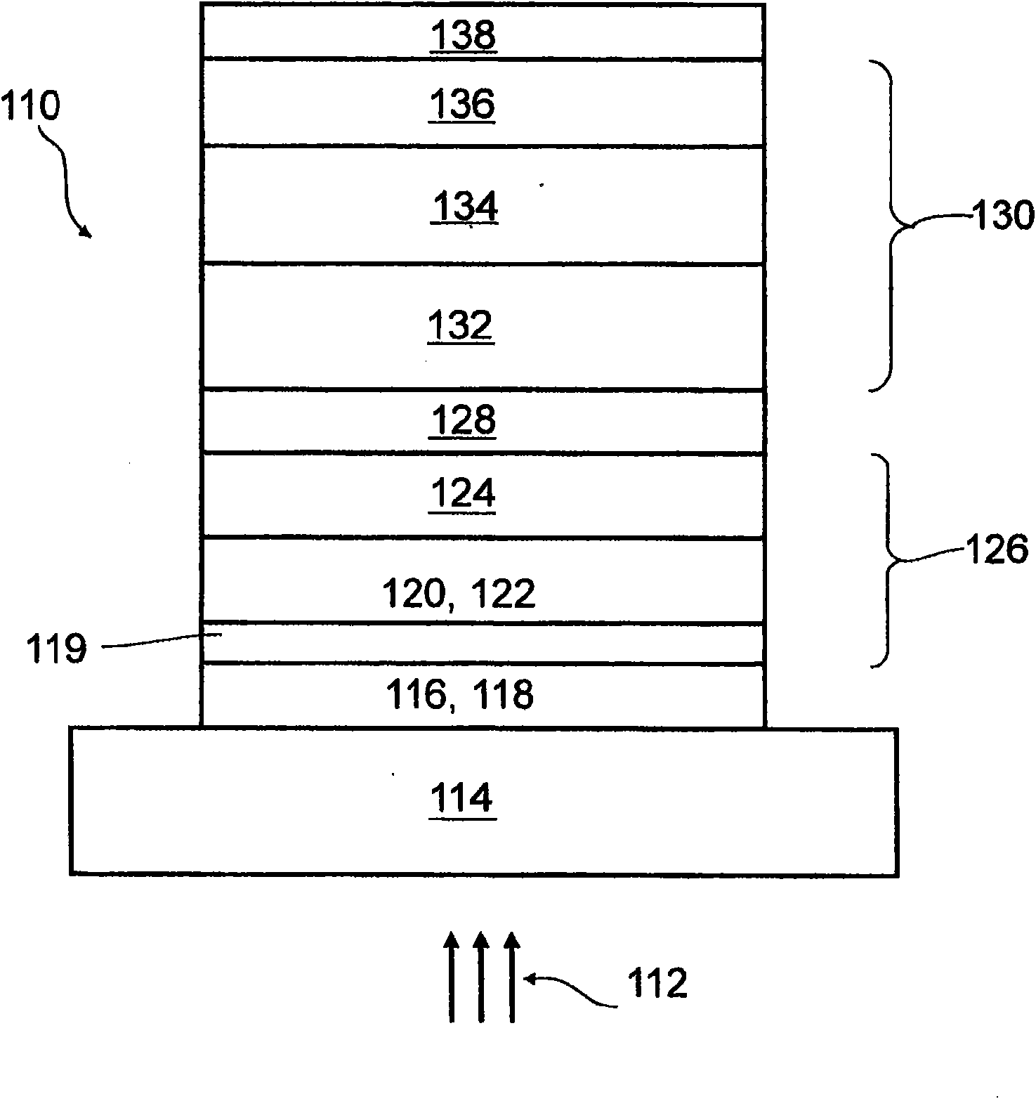
[0160] figure 1 A first example of a tandem solar cell 110 is shown. The tandem solar cell 110 includes a support 114 that is substantially transparent to light 112, preferably solar radiation. As already partially explained above, the support 114 may be, for example, a glass substrate, a transparent plastic substrate (eg, a polyethylene sheet, a PET sheet, a PTFE sheet, or other types of plastic), or a laminate of such materials, or other materials. . It should be noted that in different figure 1 In the structure of the exemplary structure represented, for example, in which figure 1 In structures where the solar incidence is from above, the transparent support 114 is not necessary, so other types of supports may be used for the structure. However, in figure 1 In the example shown, transparency of the support 114 is necessary.

[0161] In this example, a transparent conductive oxide (TCO) 116 is applied to the support 114 . It is assumed below that the TCO 116 in th...

example 2

[0195] Figure 5 with 6 Another example of a tandem solar cell 110 of the present invention is shown. Figure 5 shown with figure 1 Schematic illustration of a similar layer structure. Image 6 shows the test data for this structure, which corresponds to Figure 4 Figures in are similar.

[0196] Figure 5 The layer structure shown in first essentially corresponds to the figure 1 The layer structure, so for the functions of the layers shown, you can basically refer to figure 1 description of. The metal selection and layer fabrication sequences are described below. according to Figure 5 Instance of the layer structure with figure 1 The significant difference is that an electron transport layer 129 has been inserted between the charge recombination region 128 and the organic solar cell 130 (here, the acceptor material 132 of the organic solar cell 130) in order to improve the connection between the charge recombination region 128 and the organic solar cell 130. e...


PUM

PropertyMeasurementUnit
thicknessaaaaaaaaaa
thicknessaaaaaaaaaa
particle sizeaaaaaaaaaa

Abstract

A photovoltaic element (110) is proposed for conversion of electromagnetic radiation to electrical energy and has a tandem-cell design. The tandem-cell design comprises the following: a dye solar cell (126) with a first electrode (118), an n-semiconductive metal oxide (120), a dye (122) which absorbs electromagnetic radiation in a first spectral range and a solid p-semiconductor (124); and an organic solar cell (130) with an acceptor material (132) and a donor material (134), with the acceptor material (132) and/or the donor material (134) comprising an organic material, with the organic solar cell (130) also comprising a second electrode (138) on a side opposite the dye solar cell (126), with the organic solar cell being designed to absorb electromagnetic radiation in a second spectral range, which is at least partially different from the first spectral range, with the first electrode (118) and/or the second electrode (138) being at least partially transparent for the electromagnetic radiation.

Description

technical field [0001] The invention relates to a photovoltaic element with a tandem cell structure according to the preamble of claim 1 . Such photovoltaic elements serve to convert electromagnetic radiation, in particular sunlight, into electrical energy. Background technique [0002] The direct conversion of solar energy to electricity in solar cells is generally based on the so-called "internal photoelectric effect" of semiconductor materials, i.e., by absorbing photons and separating positive and negative charge carriers at p-n junctions or Schottky contacts electron-hole pairs. Thereby, a photovoltage is generated, which can induce a photocurrent in an external circuit, and the solar cell outputs its electric power through the photocurrent. [0003] Typically in this case the semiconductor absorbs only those photons with energies above the bandgap of the semiconductor. Thus, the size of the semiconductor bandgap determines the fraction of sunlight that can be conver...

Claims


Application Information

Patent Timeline
Patent Type & Authority Applications(China)
IPC IPC(8): H01G9/20H01L51/42
CPCH01L51/0053B82Y10/00Y02E10/542H01G9/2009H01L51/4226H01L51/0037H01L51/0047H01L51/424H01G9/2072Y02E10/549H01L27/302Y02P70/50H10K30/57H10K85/1135H10K85/215H10K85/621H10K30/20H10K30/151
Inventor N·G·普希雷尔F·艾克迈尔J·舍恩布姆J·H·黄M·卡尔松I·布鲁德
Owner BASF AG
Why Eureka
Try Eureka